|
|
QSK Amplifier Controller |
|
|
|
QSK Amplifier Controller |
|
(Updated 22 May 2015)
|
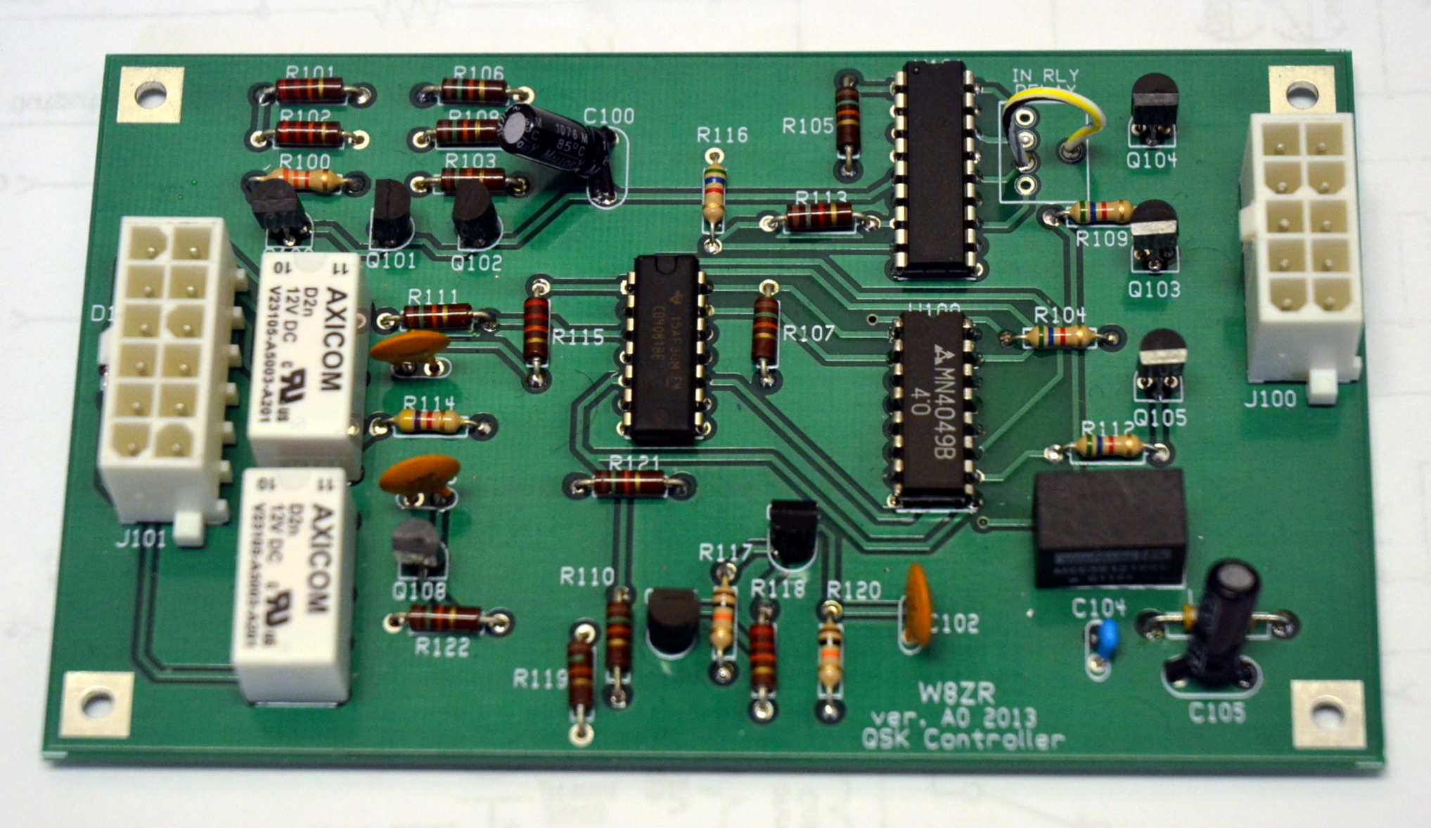
This webpage provides complete information about my QSK project, "Add Full Break-In Keying to your Linear Amplifier," that appears in June 2015 QST. This page includes all the information from the original article, plus other details and background information. I've arranged for Harbach Electronics to sell bare circuit boards, as well as full component kits. This QSK circuit is easy to build and can readily be retrofitted into most existing linear amplifiers. It also is just the ticket for incorporating QSK into a homebrew amplifier. Download Expanded QST Writeup, High Resolution Schematics, Parts Lists: You should start by downloading the expanded QST article HERE , which includes background information, a brief tutorial on QSK design and additional construction information that QST print limitations do not allow. Download high resolution schematic diagrams HERE. Download complete parts lists (in Excel Spreadsheet form) HERE. Order Printed Circuit Boards and Parts Lists: I've arranged for Harbach Electronics to make bare printed circuit boards and also complete parts kits available for builders. Click HERE to go to the Harbach site for ordering. Note that the supplied circuit board is Revision B0, which has several layout improvements over the circuit board in the article. If you find any discrepancies between the QST article and this website, then use the information from this website, which is always the most current available. ERRATA: The circuit diagram published in QST omitted protection diodes across the vacuum relay coils. Click HERE to download a diagram showing the hookup for protection diodes, and their part numbers. Diodes are required to protect the QSK switching transistors from the inductive voltage spike that occurs when the relays open. If you use the schematic diagram and the parts list from this website (recommended), it does show the required diodes.
|
 |
|
The QSK design uses Jennings RJ1A vacuum relays for amplifier input and output switching. Builders can reduce the project cost by using inexpensive open frame relays for amplifier input switching, where power requirements are typically 100 Watts. At the right is a timing diagram for an inexpensive ($3) TE Connectivity relay rated at 3A, which is more than adequate. The switching time for this relay is about 4.7mS, which is slower than an RJ1A, but still fast enough for reasonable QSK speeds. The relay is available in both 12V and 24V versions. The Mouser part number for the 24V version is 655-V23105A5505A201. |
|
|
|
Many builders want to know if open frame relays can be used for amplifier output switching. To the left are timing diagrams for two popular inexpensive and fast open frame power relays. The yellow trace is a Panasonic relay (Mouser p/n 769-JW1FSN-DC12V), and the blue trace is a TE Connectivity/Schrack relay (Mouser p/n 655-RTB14012F). Although these relays are affordable ($4) and can easily handle legal limit power, their switching speeds of 8mS and 10mS make them unsuitable for QSK above roughly 15wpm. They are also noisier than vacuum relays. Thus, while they can be used for slower speed QSK and are fine for SSB operators, they are not well-suited for high speed QSK operation. I doubt you will find faster open frame relays than these. |
|
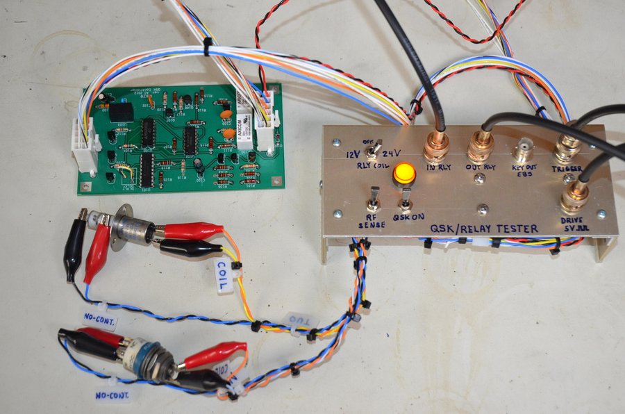
For this project, I evaluated the switching times and contact bounce of several dozen vacuum relays using the homebrew "QSK relay tester" shown at right. The tester is used in conjunction with the QSK controller PCB and allows the timing characteristics of two relays to be compared. In the photo, Jennings RF1d and RJ1A relays are being compared. A Rigol DS1102E digital oscilloscope displays the timing characteristics.
|
|
|
|
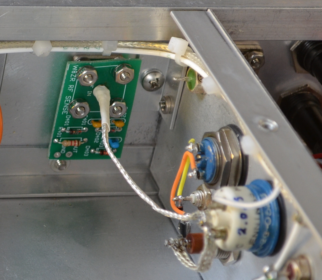
A small RF sensing circuit mounts on the back side of my homebrew amplfier's BNC input connector. Harbach Electronics supplies a PCB designed to mount on the UHF (SO-239) connector, found on the majority of commercial amplifiers. In my homebrew amplifiers, I use a UHF connector for the RF output and a BNC connector for the RF input, so I don't accidentally (and disastrously) confuse them when I'm attaching cables. The photo also shows the two RJ1A vacuum relays, mounted back-to-back on a side partition. The relays are mounted with grommets to provide sound insulation.The output RJ1A is nearest to the amplifier back panel. |
|
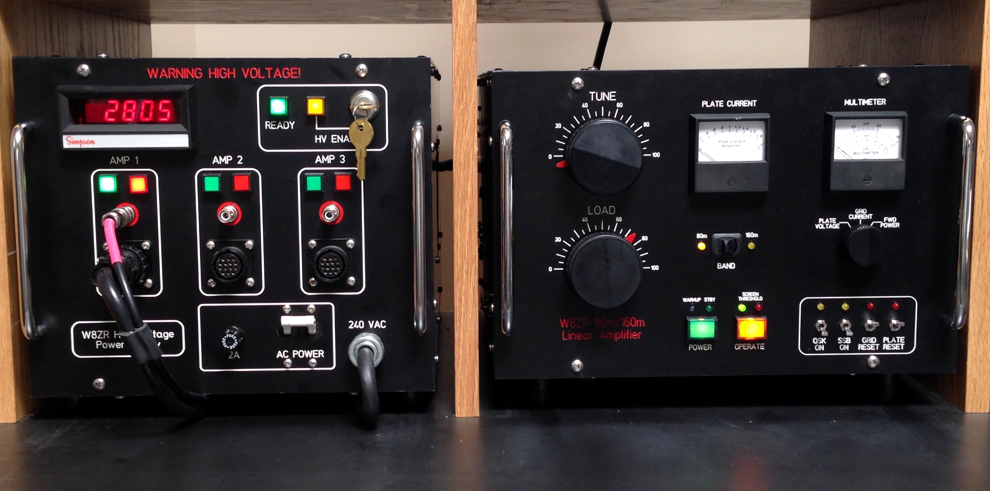
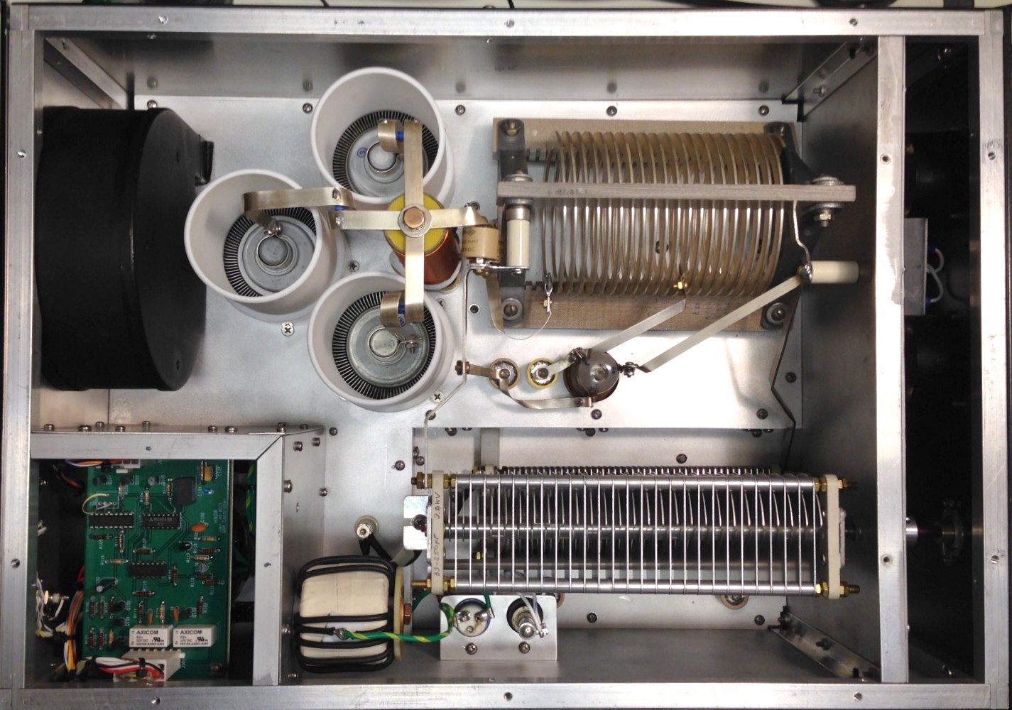
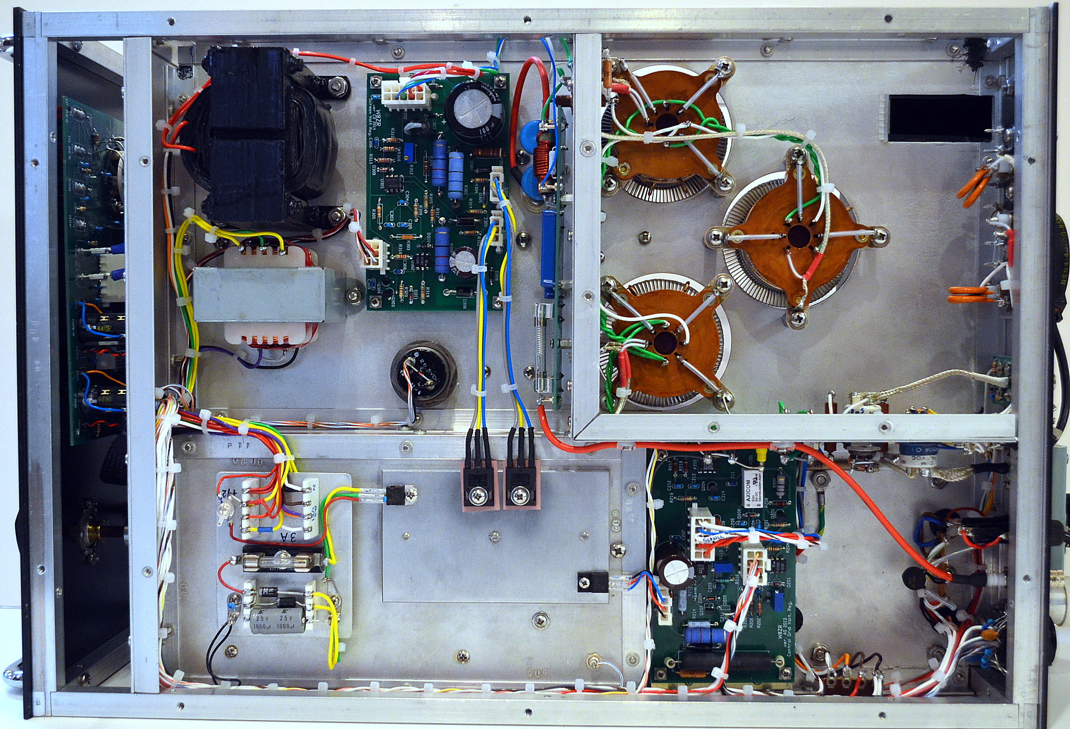
I've used this QSK circuit in two homebrew amplifiers. Below are photos of my newest amplifier (with its matching power supply), which was completed in 2014. It is a duoband 80m/160m amplifier designed for heavy duty contest operation. It uses three Russian GU74B tetrodes in a Pi-L configuration. Vacuum relays are used for both bandswitching, and QSK T/R switching. (A planned future website will show complete details of this amplifier). Below is a top view of the homebrew amplifier. The QSK controller PCB is in a shielded sub-compartment in the lower left of the photo. (The twin RJ1A vacuum relays are below the chassis, visible in the bottom photo.) The blower cage is above the QSK compartment, and Teflon sleeves vent the cooling air through the three GU-74B tetrodes. The large toroid coil is the "L" inductor for the Pi-L tank circuit, while the Pi inductor is from a Gates AM broadcast transmitter, which was scaled down and tapped to provide the correct inductances for 80m and 160m. The amplifier easily provides 1500W output, continuous duty, with significant reserve headroom.
Below is a bottom view of the amplifer. The adjustable (325V nominal) screen grid regulator is in the upper left, beside the screen voltage transformer; the -120V control grid bias regulator (switchable to lower voltages for CW and SSB) is in the lower right. The RJ1A vacuum relays mount on the bottom side of the GU-74B sub-chassis. The amplifier uses two plate chokes, a 230uH choke on top and an additional 82uH choke below. It, along with HV monitoring circuitry and three HV fuses (900 mA/5kV fuses in parallel) are on a side-mounted printed circuit board to the right of the screen grid regulator board. The front panel control, reset, and timing circuits mount on a printed circuit board visible in the left front panel subcompartment. A 12V control voltage regulator is visible at the lower left of the main chassis.
|
|
|
|
|
|
|
|
| Final Note: I know many of you would like step-by-step information on how to install this QSK circuit into your existing Ameritron, Kenwood, Drake, Collins, Heathkit, etc., amplifier. Unfortunately, at this time I can only provide general instructions that apply to all amplifiers. However, if you complete the installation of this circuit on your, e.g., Heathkit SB-220 or Drake L4-B, then I'm happy to post your photos and writeup on this website for other builders. Also, if I receive enough comments and suggestions (just email them to me), I'll also post those of general interest. I'm always happy to hear from builders of my projects (you can check out others by following the links on my home page).Thanks, and happy building! -Jim W8ZR | |
![]()
![]()
![]()
![]()

.JPG)
 & RTB14012F(12V)(BLU).JPG)