|
|
High-Power Antenna Tuner |
|
|
|
High-Power Antenna Tuner |
|
|
This homebrew legal-limit antenna tuner is based on the famous "Ultimate Transmatch" introduced by the late Lew McCoy, W1ICP. The Ultimate Transmatch was described in the "Beginner and Novice" section of the July 1970 QST (Page 24). The circuit proved so popular that it was also featured in generations of the ARRL Handbook from the 1970s. Other references can be found in November 1973 QST (page 11), and the 1973 ARRL Handbook (page 583). |
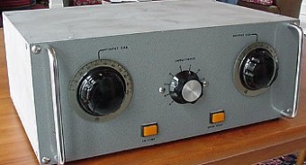
The only controls on the tuner are the tapped inductor switch and the two tuning capacitors. The two indicator lights are controlled by the main station switching console and show whether the tuner is on-line or using open-wire transmission line. The cabinet is homemade. |
|
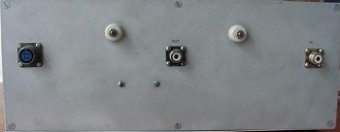
This rear view of the antenna tuner shows the RF input SO-239 connector, the output SO-239 for unbalanced (coax fed) antennas, and two high-voltage ceramic feedthrough insulators for open-wire transmission lines. The insulators are spaced for six-inch 600 ohm feeders. |
The "Ultimate Transmatch" was based on a variation of the simple T-match, with the input RF fed to the mid-point of a split-stator capacitor. Subsequent experimentation showed that the split-stator design was not really necessary, and in later designs it was replaced with an ordinary single-stator capacitor. The other innovation in the design was the use of a 4:1 toroidal balun for open-wire transmission lines. The user ordinarily strapped the toroid to the unbalanced output of the tuner. (In the tuner shown here, a Jennings RB2 vacuum relay accomplishes this task.) Although legions of commercial antenna tuners have copied the output toroid idea, the ARRL is now recommendaing a different design (introduced in the 1999 ARRL Handbook), in which the toroid is placed at the input of the network. This improvement results in less voltage stress on the toroidal transformer since it always sees 50 ohms at its input, although it has the disadvantage that it is in the circuit at all times, even with unbalanced loads. |
|
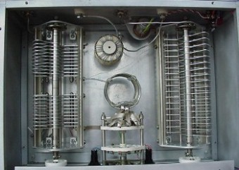
This interior view shows the dual split-stator (250 pF/section) Millen 16250 capacitor on the left, and the 200 pF Millen 16520A capacitor on the right. The 4:1 output toroid inductor is mounted just behind the tapped inductor, and is switched into the circuit by the Jennings RB2 vacuum relay, which is mounted on a bracket to the rear panel. |
|
|
The T-match is an extremely versatile circuit, capable of matching almost anything (hence the "ultimate" in the name). However, computer simulations have shown that the T-match must be used carefully, since for low impedance loads, especially, it can absorb large fractions of the transmitter power. Thousands of homebrew antenna tuners have been based on the Ultimate Transmatch design. In the version shown here, I used a tapped inductor (instead of a roller inductor) to facilitate rapid bandswitching. I also did not incorporate an SWR indicator, since I normally monitor forward and reverse power in my station with a dual-section Bird wattmeter. Although this antenna tuner has served me well for many years, I am replacing it with a homebrewed microprocessor-controlled autotuner with expanded (160 meter) frequency coverage. |
|
![]()
![]()
![]()