Inside the Multicontroller
Project History
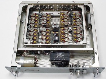
I'd long wanted a convenient way to switch between my various HF receivers. In my vintage AM station, for example, I use a Hammarlund PRO-310, a military R-390A, a Hallicrafters SX-115, and a Collins 51S-1. Changing receivers involved climbing behind the desk and swapping a snarl of cables. Although I've used a 1960s vintage military multicoupler (right), it was an awkward size (19 inch rack mount), generated heat, and didn't have any provisions for receiver muting. There had to be a better solution.
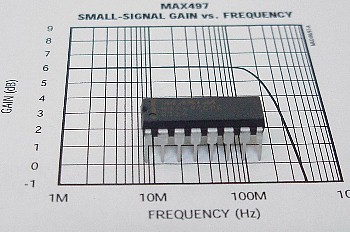 |
The idea for the multicontroller really took off when I came across the data sheets for the Maxim MAX497 integrated circuit (left). Although this IC, a quad video driver/buffer, wasn't intended as an HF amplifier, its specifications suggested that it ought to work for my application. Still, I had doubts. Would the chip's internal noise be low enough not to degrade weak signals on the HF bands? I ordered two samples from Maxim to find out. |
|
Unfortunately, because of the ICs UHF frequency response, I couldn't just breadboard a test circuit. So, not knowing whether the chips would work in this application, I gambled and started laying out the circuit boards right from the get-go. This turned out to take longer than I thought because I wanted to make the multicontroller easy for others to duplicate. |
|
|
To make the multicontroller easy to build, I felt it was important (a) to minimize point-to-point wiring, (b) to use off-the-shelf readily available parts, (c) to devise a plug-and-play circuit that required no tweaking, alignment, or special test equipment, (d) to provide builders with printed circuit boards and an enclosure that required no metal work or panel labeling, and (e) to write up detailed assembly instructions. |
|
|
I went through three reworks of the circuit board layout and three sets of prototype boards before I was finally happy with the design. Thankfully, the MAX497 chips worked great!. Although I haven't tried to measure their noise figure, in many on-the-air tests I've never been unable to hear weak signals because of the slight extra noise they contribute. Even more importantly, I've never burned one out, even during Ohio's thunderstorm season. But the preamplifier circuit gave me fits. The first version used a Mini-Circuits ERA-1 amplifier, and the second a Mini-Circuits MAV-11A amplifier. These ICs worked fine until there were area thunderstorms, and then they would inevitably die. Part of the problem may have been my circuit board design (these ICs work up into the GHz range and need very careful layout), and part may have been that those ICs were just too fragile for this application. |
|
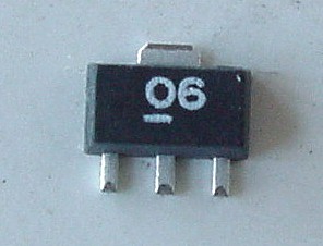 |
Finally, Mini-Circuits announced their robust new GALI-6 amplifier (left), and the problem was solved. Just to be on the safe side I added a pair of high-speed Schottky diodes to protect the preamp's front end. I've run several of the preamps for months on end, now, and have never had a failure. |
|
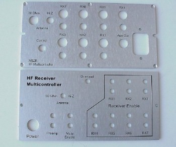
The other design challenge was to get the circuit board dimensions exactly right. The multicontroller's circuit boards are designed to slide into cabinet slots and plug together without using mounting hardware. All the circuit board header pins had to line up exactly and be fully meshed into their mating connectors when the front and rear panels were mounted on the cabinet. I must have remeasured the dimensions a dozen times before placing a quantity order of circuit boards, because the last thing I wanted was to have 100 lbs of expensive but useless circuit boards sitting in my basement! |
|
| Once I had the multicontroller working, I did a self-destruct test on the mute relay circuits (right). I rigged up a square wave generator to cycle the relays thousands of times while varying the load on their contacts. Using an external power supply I stressed the contacts by raising the voltage and current load until the contacts finally fused together, and then noted the maximum voltages and currents. |
 |
|
Fortunately, the little relays worked fine at 120VAC, and could reliably switch an external Dow-Key 120VAC relay. They also worked well up to 100 VDC, which is adequate for muting almost any receiver. I hated to wreck one of my prototypes this way, but I wanted to find any design weakness before it was discovered by other builders. As for the cabinet, I researched commercial enclosures but decided I wanted something classier than the ubiquitous MFJ-like clam shell design. Eventually I settled on a extruded aluminum enclosure by Buckeye-Shapeform (model 6ERCP-704-ANO). The folks at Buckeye-Shapeform are great to work with and did the custom panel punching and silkscreening for me. The cabinets are not cheap (but not exhorbitant either, considering their quality), and they are rugged and beautiful. You really do get what you pay for! My one regret about this project is that I can't supply a complete parts kit, which I know builders would like. Unfortunately, with the demands of my job, I just don't have the capability to sort thousands of components into little bags. However, I've tried to do the next best thing, which is to supply "semi-kits" and make it very easy for builders to order the remaining components. Still, I know it's a hassle for folks not to be able to order complete parts kits, and for that I apologize. |
|
|
Lastly, I want to acknowledge the help of two of my buddies, Dan Redman K8DR and Jerry Pittenger K8RA. Dan and Jerry served as guinea pigs by wiring up prototype multicontrollers and gave me many helpful suggestions for simplifying and clarifying assembly instructions. |
I welcome email comments and suggestions. Thanks for looking!