StationPro Circuit Description
(To follow this description, you should download and print the StationPro's circuit diagrams. Click one of the following links to download either the SP-I schematic package, or the SP-II schematic package. These will open in a new window.)
I. StationPro I Schematic Diagrams:
The circuit diagram of the SP-I is in six sheets, whose contents are as follows:
|
CONTENTS OF SP-I SCHEMATIC PACKAGE |
|
|
Sheet 1 |
Block diagram of the SP-I, showing the interconnections between the controller, RF relay unit and the transceiver pods. |
|
Sheet 2 |
Block diagram of the SP-I's controller unit. |
|
Sheet 3 |
Schematic diargram of the StationPro main printed circuit board. The same board is used in the SP-II. |
|
Sheet 4 |
Front panel schematic diagram of the SP-I. |
|
Sheet 5 |
Rear panel schematic diagram. The same board is used in the SP-II. |
| Sheet 6 | Schematic diargram of the remote RF relay unit. |
The StationPro I's controller circuitry is contained on three printed circuit boards. The main circuit board houses the bulk of the circuitry, while the front and rear panel circuit boards contain primarily the controls, LED indicators and input and output connectors. In addition, a small jumper circuit board plugs into the main printed circuit board. This jumper is removed and replaced by a microcontroller circuit board when ugrading an SP-I to an SP-II.
I. StationPro II Schematic Diagrams:
The circuit diagrams of the SP-II is in seven sheets, whose contents are as follows:
CONTENTS OF SP-II SCHEMATIC PACKAGE |
|
Sheet 1 |
Block diagram of the SP-II, showing the interconnections between the controller, RF relay unit and the transceiver pods. |
Sheet 2 |
Block diagram of the SP-II's controller unit. |
Sheet 3 |
Schematic diargram of the StationPro main printed circuit board. The same board is used in the SP-I. |
| Sheet 4 | Schematic diagram of the microcontroller circuit board of the SP-II |
Sheet 5 |
Front panel schematic diagram of the SP-II. |
Sheet 6 |
Rear panel schematic diagram. The same board is used in the SP-I. |
| Sheet 7 | Schematic diargram of the remote RF relay unit. |
The StationPro II's controller circuitry is contained on four printed circuit boards. The main circuit board and the microcontroller circuit board house the bulk of the circuitry, while the front and rear panel circuit boards contain primarily the controls, LCD display, LED indicators and input and output connectors.
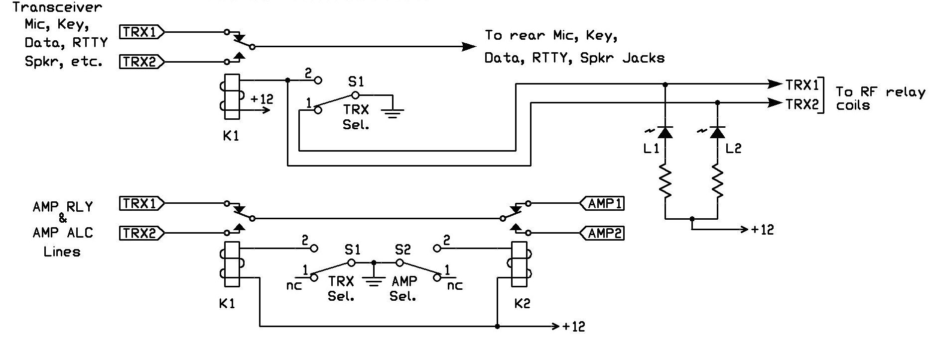
Comparison of the StationPro I and StationPro II: The differences between the switching circuits of the StationPro I and the StationPro II are shown in the next two diagrams. The following figure is a simplified switching diagram of the StationPro I. Inputs from either of two tranceiver/exciters, shown schematically in the figure as TRX1 and TRX2, are switched by relay K1. In practice, K1 is actually twelve DPDT relays, which switch a total of 24 control functions, all dedicated to DC, audio, and data signals from each transceiver. None of these lines switch RF; all RF switching is done by power relays in a separate enclosure which are controlled by the StationPro.
K1 is activated by a front panel toggle switch labeled “TRX Sel." in the figure, which grounds the coils of K1 when TRX2 is selected. In addition to activating K1, this switch also illuminates the front panel LED indicators and grounds the appropriate line that controls the remote RF relays for the two transceiver/exciters.
Most of the 24 lines from TRX1 or TRX2 are directly routed to front and rear panel jacks on the StationPro. The exceptions are two lines that are intended to control linear amplifiers, shown on the diagram as AMP RLY and AMP ALC. As shown in the bottom half of the above figure, these two lines are routed by additional poles on relay K1 to one of two amplifers, selected by switch labeled “Amp Sel.” Although it is not shown on the diagram, the “Amp Sel” switch also grounds the lines that control remote RF relays for switching either amplifier in or out of line.
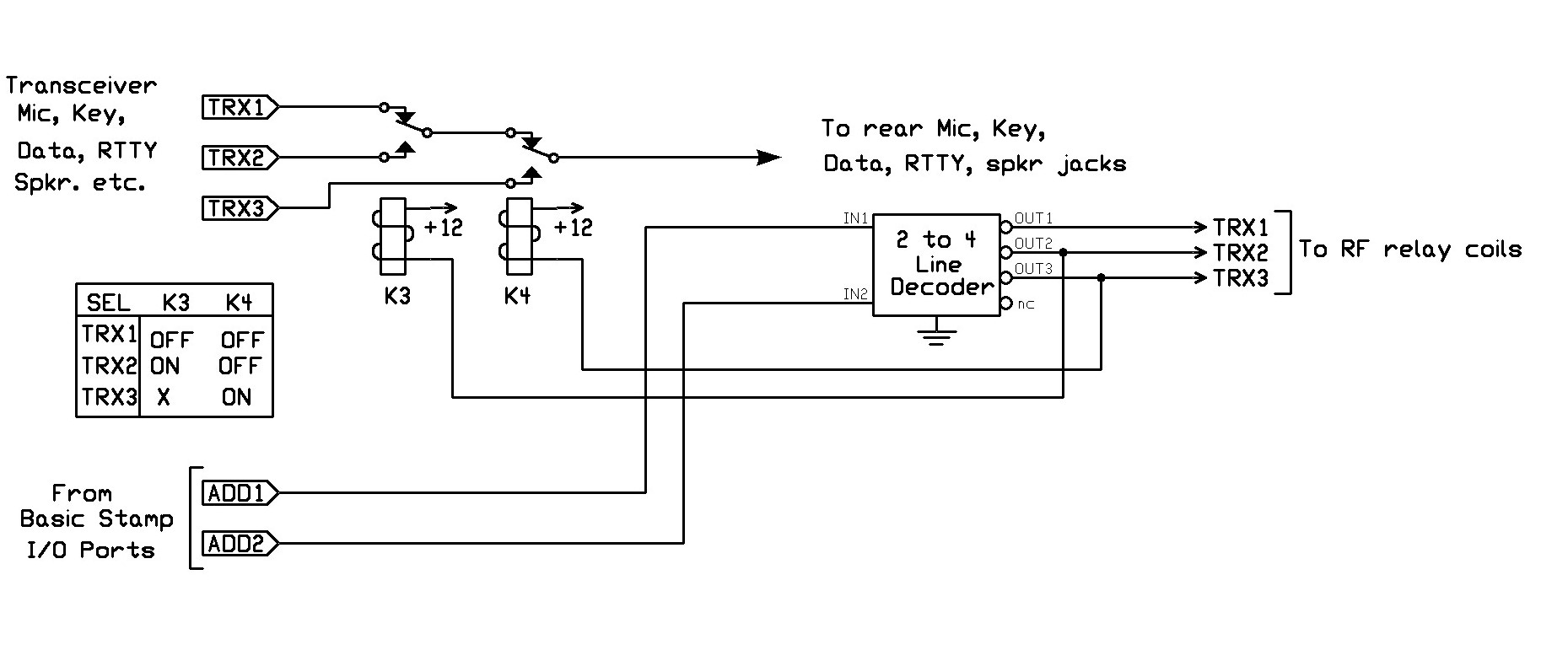
The above figure illustrates the simplified switching of the StationPro II, which allows independent selection of three transceiver/exciters, shown as TRX1, TRX2, and TRX3, and three amplifiers AMP1, AMP2, and AMP3 (not shown in the diagram). Relays K3 and K4 in the figure are each actually twelve DPDT relays. The coils in these relays are controlled by two output ports on the Basic Stamp BS2IC microcontroller, described below. These ports output either a logic H or L, in four possible combinations, and these outputs are applied to the input address ports of a 2-to-4 line decoder. This decoder grounds the appropriate output line, thus activating either K3 or K4, and also grounding the control line for the external RF relays. The inset in the figure shows the state of K3 and K4 for the three transceiver/exciters. Amplifier switching in the StationPro II is not shown in the diagram, but done in a similar manner to the TRX switching; address lines from the Basic Stamp are decoded and used to activate the amplifer switching relays.
This relay configuration makes it easy for a builder to upgrade from the StationPro I to the StationPro II. The main circuit board is identical in the two designs, and upgrading entails plugging a control circuit board into the main circuit board, and swapping the front panel circuit boards.
Amplifier Relay Keying: Amateur transceivers have an amplifier keying output to allow control of an external linear amplifier. In newer transceivers, this keying circuit often has modest current and voltage limitations that make it unsuited to controlling older amplifiers whose relays work at higher voltages, or at negative DC or AC voltages. For example, the still-popular Collins 30L-1 amplifier uses a relay that operates at about -170VDC, whereas that in a vintage National NCL-2000 amplifier operates at 6 VAC. Because the StationPro is designed to accommodate all transceivers and amplifiers, it incorporates a flexible amplifier keying circuit that will work with any amplifier and places no stress on a transceiver’s keying circuit.
Referring now to the main circuit board schematic, we see that closing the amplifier keying line grounds the resistor string R102, R103, and R105. The open-circuit voltage of the keying line is 12V and the closed-circuit current is about 5 mA. The voltage developed across R102 causes Q101 to conduct, raising its collector voltage to about 7.5V and illuminating the internal LED in solid state relay K114. The current through the LED is limited by R106 to about 6 mA. The bidirectional MOSFET switch in the output of K114 closes in less than 3 mS and closes the amplifier keying relay of a selected linear amplifier. K114 is rated at 400V AC or DC of either polarity, and 250mA, which is adequate for almost any application. Diode D109 provides an interlock function which keeps K114 from closing when the amplifier bypass relay in the RF relay unit is enabled.
The main printed circuit board includes provisions for the builder to use an alternate amplifier keying circuit, shown in an inset in the schematic diagram. This circuit, which must be selected during assembly, uses a power MOSFET Q102 in lieu of K114. Q102 can switch 200V at up to 3A, but can only be used for positive voltages. D108 is a snubber that protects Q102 from negative voltage spikes caused by a selected amplifier’s keying relay. Most builders will choose to use the default circuit.
Remote RF Relay Circuits: All RF switching in the StationPro is done by RF power relays housed in a remote relay enclosure. As shown in the circuit diagram (the same circuitry is used in both the SP-I and SP-II), this enclosure houses ten identical SPDT power relays. (Only seven of these relays are used in the SP-I.) When a transceiver is selected, the corresonding relay routes its RF output either to the input of a selected linear amplier or to bypass relay K310. Other relays route the output of the selected amplifer to the RF output jack Note that the outputs of non-selected transceivers are grounded in order to protect their receiver input circuits, as are the inputs of non-selected amplifiers. The outputs of non-selected amplifiers are left floating. All relays are enabled by the StationPro’s control unit, via an ordinary 8-conductor “CAT 5” ethernet cable. The power relays used in the RF switching enclosure are rated at 12A (DC) and have been extensively tested for reliability, power-handling capacity, and negligible insertion loss throughout the HF bands.
For builders wishing to view their transmitted signal on a monitor oscilloscope, the circuit board pattern of the RF relay unit has provisions for sampling the transmitted RF. Capacitors C509 and C510 are a capacitive voltage divider that samples the transceiver output, while C511 and C* sample the amplifier output. C* is a 2.8 pF capacitor built into the circuit board pattern. If desired, it may be reduced to 1.4 pF by cutting a trace on the circuit board.
Optional RF Relay Provision: The StationPro’s remote RF switching unit uses printed circuit-mount power relays having 12V coils. Although these relays easily handle the U.S. amateur legal power limit of 1500W (they have been tested to 2500W on the HF bands), some builders may prefer to design their own RF switching unit using vacuum relays that typically operate on 24-28 VDC. The StationPro has a rear panel power jack for powering such relays. If used, D105 and D106 automatically route the higher voltage to the remote relay enclosure. If the standard 12V enclosure is used, then nothing should be connected to this jack.
Microcontroller Circuitry (SP-II): Control functions in the StationPro II are implemented by U201 a Basic Stamp BS2IC microcontroller, whose source code can be viewed HERE. The source code, which is uploaded to the Basic Stamp' internal interpreter during assembly, is extensively annotated and the logic flow can be understood easily by builders familiar with the Stamp’s P-BASIC programming language.
When the StationPro II is powered up, the nine momentary-action front panel switches S303-S311 are scanned by U201, which then executes the requested action when a depressed switch is discovered. When a transceiver or amplifier is selected, U201 places a LOW (nominally 0V) on the appropriate inputs of the 2-to-4 line decoders U202a and U202b. The output of the decoders are inverted by U203 and buffered by darlington power driver U204, whose outputs ground the coils of the selected relays.
The StationPro II has networking capability for controlling complex stations with many rigs. One output port of U201, designated REMOUT on the schematic diagram, outputs a 100 mS LOW pulse to the remote in/out jacks J202 and J203 when any of the momentary action switches is depressed. This pulse is detected by other StationPro IIs in the operator’s station (up to three StationPro IIs can be networked), which signals them to go off-line.
U201 can generate a pulsed audio tone (alternately, a two-tone audio tone) which is routed through a level adjust trimpot R204 to the StationPro II’s microphone audio line. This tone is used to facilitate amplifier tuning.