|
REPAIRING THE HRO-600 posed an unusual challenge because of the manual's scanty documentation. Although it provided a receiver block diagram and a brief overview of the plug-in modules, the manual had no module schematic diagrams.
Furthermore, the ICs in the defunct sythesizer were from long-discontinued Motorola IC family called "MECL II" and data sheets and pinout diagrams were very hard to find.
I literally had hams from around the world searching their bookshelves and file drawers to help out, and one-by-one the data started to arrive. My last needed data sheet came from an Israeli amateur. With his and many other ham's generous assistance, I finally had the specs on all the mystery ICs. It's sure a good thing so many hams are pack-rats!
|
|
|
|
|
 |
|
|
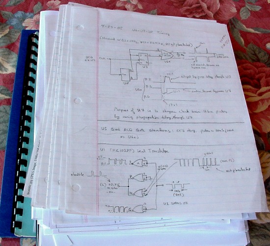
Once I had the data sheets, then I had to reconstruct the synthesizer's schematic diagram by reverse engineering the circuitry. Here is a step-by-step description of how it was done:
|
|
|
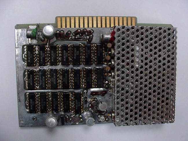
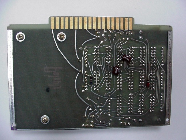
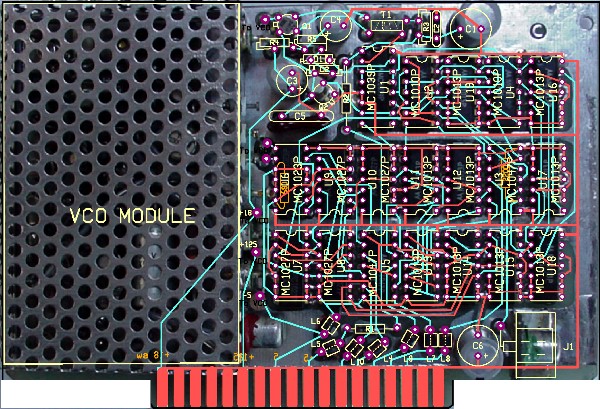
| STEP 1 was to take a digital photograph of the front and rear of the sythesizer circuit board. The shielded enclosure contains the voltage-controlled oscillator components. Fortunately, the VCO appeared to be working, since I was getting an unlocked sine wave output from it. Thus I knew the problem was somewhere in the digital logic circuitry that comprised the rest of the board. |
 |
 |
|
|
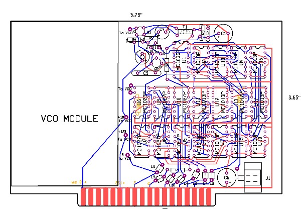
| STEP 2 was to copy manually the circuit board patterns and for this task I used a CAD software package called CIRCAD 98. (You can download a free demo version from http://www.holophase.com. ) The software has provisions for rotating and stretching photographs to remove any parallax or distartion so that the front and back photos of the board line up perfectly with each other. On the left photo, the red lines are for the top traces and the blue lines are for the bottom traces. The photo on the right shows the completed tracings. This part was a bit like making a paint-by-numbers painting. |
 |
 |
|
|
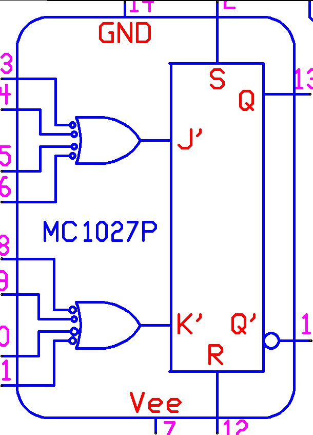
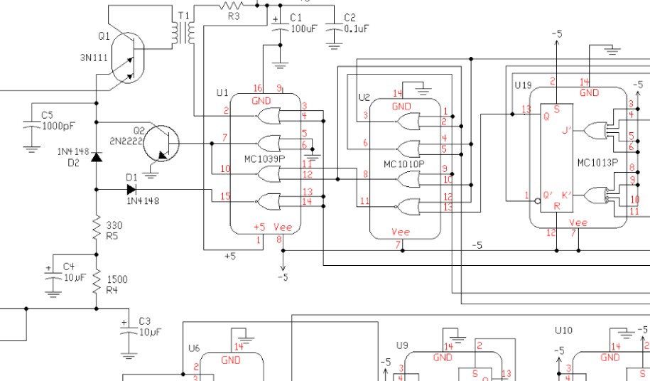
| STEP 3 is where the magic starts. Once the circuit board traces are completed, the software can create the actual schematic diagram that corresponds to the copied traces. However, in practice it's not quite as easy as it sounds, because first I had to make detailed drawings of the symbols for each component in the schematic. There are existing libraries for all conceivable modern components, but the Motorola ICs in the HRO-600 were designed in the days of punch cards and big IBM mainframes, and CAD programs were decades away. The photo shows an example of one of my home-made IC symbols. |
|
|
|
| STEP 4 was the fun part. Once the component library was finished, then Circad 98 automatically generated a circuit diagram showing all the interconnections between components. Of course, it was up to me to move the components around on the drawing to pretty it up. Moving the components around was a bit like solving a jigsaw puzzle. The secret is to find the best position for each component so one doesn't have interconnecting lines running every which way. The photo shows a small portion of the completed diagram, all told the result of six weeks of effort. (You can download a PDF file of the complete synthesizer schematic by CLICKING HERE.) |
 |
|
|
Finally, I started to work troubleshooting the circuit. With the aid of a homebrewed extender board, and with the data sheets and schematic diagrams to guide me, actually fixing the synthesizer wasn't all that difficult. Troubleshooting consisted basically of checking logic waveforms on an oscilloscope until I found one that wasn't right, and then buying a replacement IC from a company that sells obsolete semiconductors (Rochester Electronics: "Leaders on the trailing edge of technology.")
The other needed electrical repairs were minor. I replaced a shorted zener diode in the AGC circuit, realigned the wafers on the bandswitch, and replaced a broken dial cord on the MHz dial drum.
|
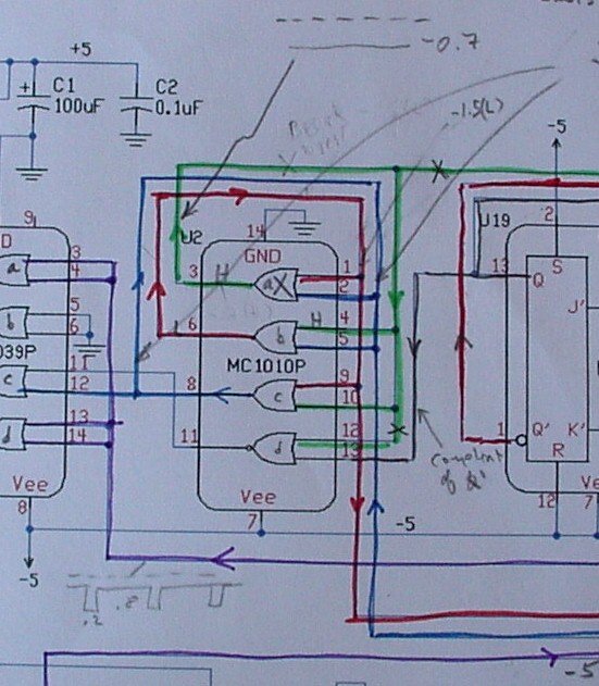 |
"X" marks the spot! It seems crazy that a bad NOR gate in an IC could have caused me to spend weeks of time buried in the basement. But I know that I never could have found the problem had I not invested that time. Ironically, it took me all of five minutes to clip out the bad IC and solder in a replacement. (As a precaution, I also replaced all the electrolytic capacitors and out-of-tolerance resistors on the board.) It was thrilling to see the synthesizer output lock at 56.000000 MHz on my frequency counter when I powered up the receiver,
Could I have just replaced all nineteen ICs at the outset and hoped for the best? (Replacement ICs cost about $15-$20 each.) In hindsight, sure. But I didn't know that at the time and, besides, this has not only been a great educational experience, but I really enjoy tinkering with new circuits.
|
| I now have a large pile of notes on the HRO-600. But here's the final irony. After I finished repairing the radio, I found a source for all the original factory schematic diagrams. The diagrams are copies of copies of copies and are quite faded, but they'll do in a pinch if my receiver ever breaks again. If you own an HRO-600, email me a picture of your radio along with your serial number and I'll mail you a CD-ROM with the schematics. I can only send CD-ROMs to HRO-600 owners, since I'm not in the manual business and don't have time to send them to the world at large. (Incidentally, printed schematics are very large-- one of them is 2 ft wide by 12 ft long. Yes, that's feet,!) Note added 04-29-2011: I've uploaded copies of the HRO-600 schematics to my website, which you can download by clicking HERE. |
 |
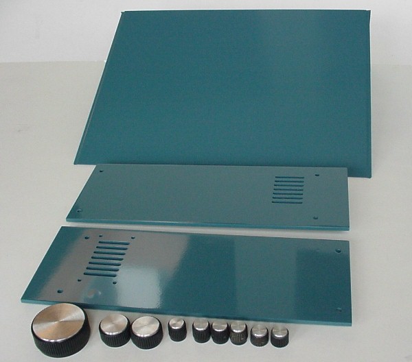 |
The cosmetic repairs were very straightforward. I had a machine shop turn down the knobs' aluminum inserts, which had oxidized over the years. In contrast to the knob inserts on the HRO-500, which are very thin spun metal caps, the HRO-600's knob inserts are 1/8" thick aluminum disks. In another forty years, maybe I'll refinish them agoin.
The last step in the restoration was to have the metal cabinet and side panels refinished at a local auto bady shop. It took a bit of experimentation for the shop owner to duplicate the color and sheen of the original paint job, but the final result is nearly perfect.
|
|
|
|
|
|
|
|
|
|