|
|
Six-Meter Linear Amplifier |
|
|
|
Six-Meter Linear Amplifier |
|
|
|
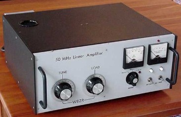
This homebrew six-meter linear amplifier started off life as a "junker" Alpha 76PA h.f. amplfier. The original Alpha amplifier was missing its two 8874 tubes, and the bandswitch and tuning capacitor had been badly arced and melted. The meter was defective, and an extra hole had been drilled in the front panel. Fortunately, blank panels and cabinet parts were available from the original cabinet supplier. I began construction by scrapping the front panel, cabinet top and side panels, and stripping the r.f. deck down to the bare sheet metal. All r.f. deck components were discarded, except the tune and load capacitor, the former being rebuilt (using the few remaining unmelted plates!) to cover 10-30 pF. The rebuilt amplier uses a single Eimac 3CX800A7 triode, and features vacuum antenna relays, new metering and control circuits, electronic bias switching, and new forward/reverse power measuring. Circuit Details: The circuit is a conventional cathode-driven (grounded grid) design. A trifilar-wound filament choke (6.4 uH, 10 turns on 1/2 in. dia. core, 2 in. long) isolates the cathode and filaments of the 3Cx800A7. The input network is a T-network, with two inductors (8 turns, 1 in. long, 3/4 in. dia) forming the bridge of the "T," and a 10-75 pF variable capacitor for the arm. Design parameters for the input network are 0.66uH for L1 and L2, and 27 pF for the arm capacitance. The plate tank circuit pi-network inductor is 0.36 uH and consists of 4 turns of 3/16 in. dia. copper tubing, 1-1/8 in. ID by 2 in. long. The 6.5 uH plate choke is 40 turns, space-wound on a 3/4 in. dia. fiberglass core, 3-1/4 in. winding length. It is in series with a 15 uH VHF supressor choke (13 turns # 20 wire, close wound). An ICE Model 426 low-pass filter is permanently attached to the rear panel to improve harmonic suppression. The original power supply was left intact, except for a new 14 VAC filament transformer, a 28 VDC bias and control voltage supply, a 3 minute "warmup" timer, and a grid overcurrent LED warning circuit. A plate overcurrent relay trips the amplifier off-line if Ip exceeds 2 Amps. A red panel lamp (above the plate current meter) lights during warmup and when the amplifier is on-line. Construction Details: An alodized aluminum cover plate for the 3CX800A7 tube socket was fabricated from a piece of the old front panel. The new silver-plated tank coil was fabricated from a section of the orignal Alpha 76PA plate inductor. The RF sampling circuit (for the wattmeter), ALC, relay and control circuits are all new. I used the original blower, which is nearly perfectly matched to the cooling requirements of the 3Cx800A7 and very quiet. All interconnect wiring in the RF compartment uses coax or shielded wire.
|
|
|
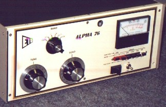
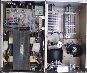
Six Meter Linear Amplifier, showing new front panel and cabinet (above), and original Alpha 76PA junker (below).
|
||
|
|
||
|
|
||
|
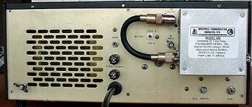
Rear panel of ampifier, showing ICE low-pass filter, ALC threshold adjust, and r.f. meter select switch. The RF input is a BNC connector, and the RF output is an SO-239.
|
||
|
|
||
|
Original "basket case" Alpha 76PA amplifier. Melted tuning capacitor is visible in this side view of r.f. compartment. |
||
|
|
||
|
|
||
|
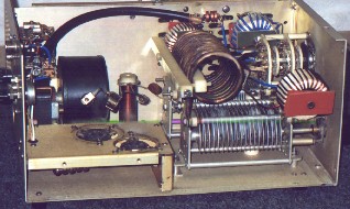
Interior of renovated amplifier. The 3CX800A7 is to the right, partially obscured by the cooling shroud. |
||
|
|
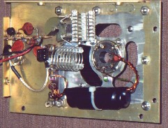
As shown in the bottom photo, the cover plate also holds the filament choke and T-input matching network. The set-and-forget input tuning capacitor is adjustable from above. The rebuilt amplifier uses two meters. One Simpson "wide-vue" meter measures cathode current, and the other measures plate voltage, grid current, or r.f. watts. A rear-panel toggle switch lets the user choose either forward or reflected power to be displayed on the meter. The amplifier tunes very smoothly, with no trace of instability. About 50 Watts are required to drive it to 800 Watts output. This project was completed early in 1999.
Visitors: |
|
|
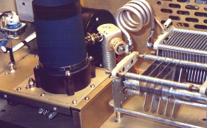
Closeup of tank circuit, showing silver-plated inductor, rebuilt tuning capacitor, tube cooling shroud and vacuum antenna relay.
|
||
|
|
||
|
Underside of subchassis, showing tube socket, filament choke, and input T-network. |