|
|
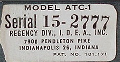
Regency ATC-1 Converter |
|
|
|
Regency ATC-1 Converter |
|
|
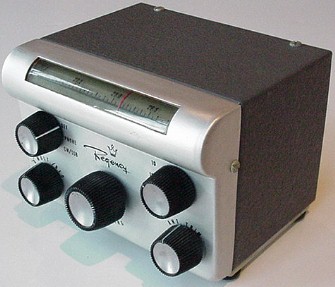
The 1956 Regency ATC-1 converter heralded the dawn of a new era for amateur radio. The little converter had only two transistors -- one PNP, one NPN, both germanium, both now long obsolete -- but they were the start of a revolution. Amateurs responding to the Regency advertisement in the August 1956 issue of CQ Magazine thought they were merely buying a novel mobile converter. In truth, for $79.50, they were buying a seminal piece of ham radio history. |
|
|
|
Regency Electronics was the brainchild of former RCA employees, Joe Weaver and John Pies. The parent company, Industrial Development Engineering Associates (I.D.E.A), was incorporated in 1947, the same year Bell Labs scientists Shockley, Bardeen and Brattain invented the transistor. |
|
In October, 1954, Regency brought to market the world's first transistor radio, the TR-1, and less than two years later, the world's first transistor amateur product, the ATC-1 converter. Unbeknownst to all, this inauspicious little device signaled for amateur radio the beginning of the end of the vacuum tube's long and glorious reign. |
|
|
Description: The ATC-1 was intended to fill a niche market for mobile operators. When Regency introduced its new converter in 1956, most hams used dedicated receivers in their vehicles, the Multi-Elmac PMR-7, the Morrow MBR-5, and the Gonset G-66 being popular mobile receivers of the day. Other companies' mobile HF converters, such as the Gonset "tri-band Converter" had never been big sellers, primarily because their vacuum tube designs offered little space savings over full-blown receivers. Furthermore, like all mobile receivers, vacuum tube converters required an external power supply. |
|
|
Regency obviously hoped that the diminuative, battery-powered ATC-1 would reverse this record. Powered by three AA penlight cells, the ATC-1 covered five bands (80-10 meters) and featured a Q-multiplier for AM reception and a BFO for SSB/CW reception. A rotating drum displayed the band in use, with single-knob tuning. Bandspread was quite adequate, with dial calibration marks every 10 kHz. The output frequency of the converter was 1230 kHz.
|
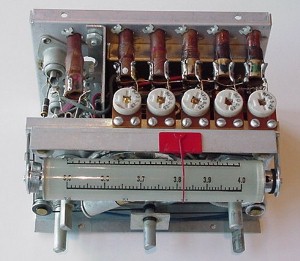
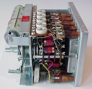
Top view of the ATC-1 with the cover removed, showing the dial drum mechanism and the indvidual tuned circuits at the emitter of mixer/oscillator transistor Q1. |
|
The ATC-1's panel bulb was lighted by pushing in on the tuning knob. The bulb was the major source of battery drain. |
Despite its simplicity, the ATC-1 was a remarkable engineering achievement. To appreciate fully this achievement, however, it is necessary to place the ATC-1's design into historical context. In the mid-fifties, the transistor's advantage over vacuum tubes was primarily in simple, portable applications, where size and power consumption were important but performance secondary. For most applications, vacuum tubes had a head start of nearly a half century, and it seemed highly improbable that transistor technology could ever catch up. Transistor usage in r.f. applications seemed particularly problemmatic.
|
|
Secondly, many engineers schooled in tube circuits found transistor circuits alien and confusing. Unlike vacuum tubes, transistors were current-operated devices. Their impedances were very low, there was little isolation between inputs and outputs, and they were prone to thermal runaway. To design with these fragile little devices, the rules of thumb, the guidelines, and the intuition developed over a professional career had to be tossed out the window. Transistors were a whole new ballgame, and the learning curve was steep. And finally, the germanium transistors of the 1950s were unimpressive performers. Their current gain was low, as was their frequency response, and they were highly temperature sensitive. And worst of all, they were oh-so-delicate. A slip of a cliplead, a tiny snap of static electricity, a battery momentarily connected backwards, and they would be gone in an eyeblink. And to make matters worse, these early transistors cost several dollars apiece. Frankly, to many design engineers, transistors were such poor performers that using them seemed hardly worth the effort. |
|
Against this backdrop, the ATC-1's design shines like a beacon. Consider that it used only two transistors to implement a circuit consisting of a mixer-modulator, tunable local oscillator, beat-frequency oscillator, and Q-multiplier. Furthermore, it covered the entire HF spectrum, to 30 MHz. And the total power consumption for all this circuitry? About two milliwatts! By comparison, the Gonset mobile converter tuned only three bands, used four vacuum tubes, had no BFO or Q-mulitiplier, and required about twenty thousand times as much power. |
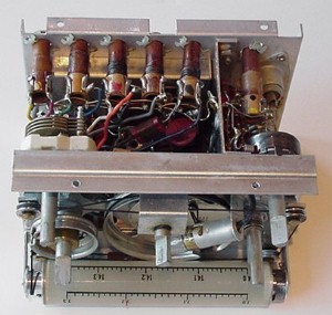
Side view of the ATC-1 showing the bandswitch and point-to-point wiring. Regency's earlier TR-1 |
|
But why a converter and not a receiver? At the time of the ATC-1's introduction, Regency had been selling the four-transistor TR-1 AM "pocket radio" for nearly two years. Why didn't Regency build a full-fledged mobile receiver, using the ATC-1 circuitry as the front end, and the TR-1's 455 kHz IF and audio stage as the back end? There are two reasons why this pairing wouldn't have worked. The first is that the TR-1's tiny speaker delivered only milliwatts of audio power, which is far less than needed in a noisy mobile environment. Redesigning the audio stage to deliver, say, 1 Watt of audio, would have made internal batteries impractical. Furthermore, the TR-1 used a 22.5V battery with a life expectancy of only about 20 hours. Given the technology of the day, it would not have been easy to redesign the radio for 6 or 12 V operation. Secondly, such a receiver would have cost as much as vacuum tube receivers, but would have had inferior performance. Lacking an r.f. stage, noise limiter, and agc control, such a receiver would likely have met with poor market acceptance. Keep in mind that the Collins KWM-1 mobile transceiver was introduced the same year as the ATC-1 and had greatly raised the performance bar. By sticking to a low-priced converter, Regency sidestepped these potential shortcomings. |
|
Circuit Description: The simplified circuit diagram, below, shows how the ATC-1 worked its magic. Signals from the antenna were coupled through transformer T1 to the base of mixer/oscillator transistor Q1. Diode D1 prevented peak RF voltages from exceeding the breakdown voltage of Q1's base-emitter junction. The use of a diode for this purpose, although common today, was an ATC-1 circuit innovation. The base of Q1 was biased by tapping the battery pack at the 3.0V point, and the 4.7K emitter resistor helped stabilize this bias point against temperature changes. Oscillation of Q1 was made possible by coupling the emitter of Q1 to the collector via feedback transformer T2. This circuit innovation made for great economy and had been used previously in Regency's TR-1 AM broadcast radio. |
ATC-1 simplified circuit diagram
|
Q2 served as the Q-multiplier/BFO. In the CW/SSB mode, the tuned circuit at the base of Q2 ( L1 and 240pF capacitor) was tuned to 1230 kHz, with the BFO level adjusted by the 20K gain control. This control also served as a kind of IF gain adjustment through its influence on the AGC of the AM radio following the ATC-1. The output of this BFO stage was injected into output transformer T3, via a 240 pF capacitor. In the AM mode, the tuned circuit was de-Q'ed with a 27 ohm resistor to prevent oscillation, and the 20K gain control adjusted the circuit's Q. CLICK HERE to display the owners manual, including a full schematic diagram, of the ATC-1 in a new window. (NOTE: requires Acrobat Reader 8.0 or later). |
![]()
![]()
![]()
![]()