|
|
Davco DR-30 Receiver |
|
|
|
Davco DR-30 Receiver |
|
|
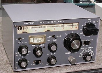
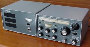
The DR-30 shown above (serial number 513) weighs only 7 lbs and measures 7x4x6 inches. A double conversion design featuring a Collins mechanical filter, the receiver uses 23 germanium PNP transistors and two FETs. The design is one of the earliest to use field effect transistors. The matching speaker/power supply pictured on the right (CLICK HERE for details) is a homebrewed clone of the factory original. |
The Davco DR-30 miniature receiver, manufactured from 1965-66, is prized by collectors for its rarity, breakthrough engineering, and mil-spec construction. Carrying a price tag of $390, fewer than 600 of these early solid-state radios were made by the now-defunct Florida company. |
|
|
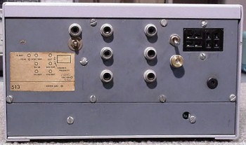
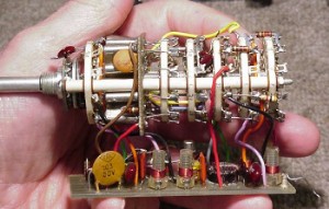
Anticipating a matching DT-20 transmitter which never materialized, Davco brought numerous signals (VFO, BFO, crystal oscillator, filter input and outputs) to the rear panel of the radio. The receiver has two antenna jacks, one for the HF bands and the other for 6 meters. The toggle switch next to the power connector allows the receiver to be used in negative or positive ground vehicles. |
History: The DR-30 was the brainchild of James A. Lovette, who developed a prototype in the early 1960s. The company was incorporated in January 1964 and backed by about $400,000 in loans from the Small Business Association and a consortium of private investors. The funds ran out in 1968, and on April 4, 1969 the company's assets were sold for $10,000 at auction. The company lingered on under new ownership until 1991 in other lines of business. |
|
|
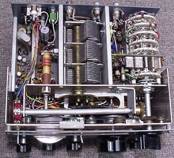
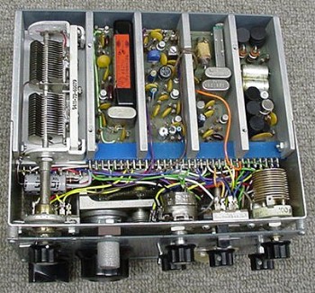
This top view shows (from right to left) the 6-section bandswitch and vertically mounted crystal oscillator, the First IF amplifier circuit board, the multisection VFO and crystal oscillator tuning capacitor, the VFO circuit board, and the 100kHz calibrator. VFO tuning reduction is by two meshed anti-backlash gears. |
Description: The DR-30 is a ham-band-only receiver that covers 80-6 meters, plus WWV, in twelve 500 kHz blocks. Two "A" and "B" ranges at any desired frequency can be user-selected. The DR-30 features a linear dial scale with 1 kHz calibration, selectable AGC time constants, tunable notch filter, a built-in noise blanker, 100 kHz crystal calibrator, and separate AM and SSB/CW detectors. Intended primarily for 12V mobile operation, the receiver draws only about 100 mA with the panel lights turned off. A matching speaker/power supply was optionally available for fixed station use. |
|
|
From left to right of this underchassis view are the preselector tuning capacitor, mechanical filter board, 2nd IF amplifier, BFO, and audio amplifier. A heavy machined block of aluminum holds the circuit boards, which slide in from the rear into the blue edge connector. |
Circuit Details: The DR-30 uses a double-conversion design with a 2.955 MHz variable IF and a 455 kHz second IF. The VFO tunes 1.950 - 2.500 MHz. Curiously, the RF stage uses a P-channel FET, while the first mixer uses an N-channel FET. All other transistors are germanium PNP types, mostly 2N993s. Selectivity is provided by three Clevite TF-01A ceramic transfilters and a Collins 2.1 kHz mechanical filter. An extra crystal sharpens up the mechanical filter response for CW use. The design incorporates a true impulse-type noise blanker, with adjustable threshold. |
|
|
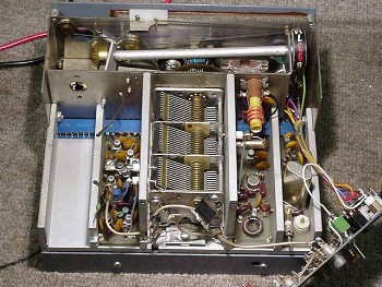
Despite its compact size, the DR-30 is relatively easy to service. Circuit boards slide out from the rear. |
The bandswitch and r.f. amplifier circuitry is easily removed as a single module. The P-channel enhancment FET is the only socketed transistor in the receiver.
|
|
|
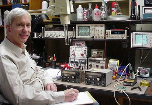
I'm smiling because I just finished the final alignment of my DR-30. Restoring the radio was an arduous task, and I never would have succeeded but for the gracious loan of a working radio by Rick, WA6NCX. |
||
|
Operating Impressions: The DR-30 is an impressive performer, given the technology available at the time. The VFO is rock-stable, and dial calibration tracks to within 2 kHz over the full 500 kHz range. As might be expected, the receiver is somewhat suspectible to front-end overload, a consequence partly of unusally high RF stage gain and the fact that AGC voltage is applied only to the IF amplifiers. The AGC thumps a bit on the "fast" setting, but generally works well. The noise blanker is effective, but the threshold must be carefully set to avoid signal attenuation. The AM audio fidelity is excellent, rivaling that of the costly National HRO-500, another early transistorized receiver. Click here to download an Adobe Acrobat (.pdf) file of the circuit diagram of the r.f. stage, modified to use an N-channel MOSFET, instead of the now-unobtainable P-channel FET. |
||
|
|
|
|