|
|
The National Radio Company HRO-600 Receiver |
|
|
|
The National Radio Company HRO-600 Receiver |
|
|
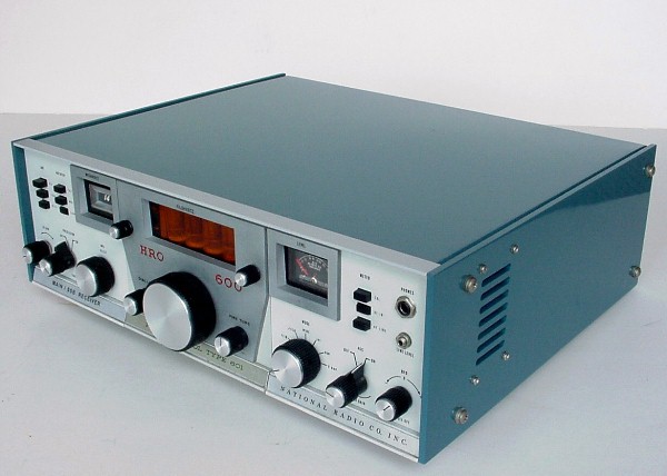
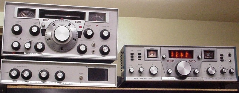
THE NATIONAL RADIO COMPANY launched its legendary "HRO" series of communications receivers in 1935 with the 9 tube single-conversion HRO. After 40 years, the HRO dynasty finally ended with the solid state, synthesized HRO-600, pictured at the right. Intended primarily for government and commercial users, and priced at $5600, the HRO-600 is today rarely seen. (Reportedly, fewer than than two hundred were manufactured.) The HRO-600 was introduced in 1970, shortly after National declared bankruptcy. The reorganized company struggled for several years, and during this period both the HRO-500 and HRO-600 were sold, primarily to government and marine customers. The HRO-600 shown here is serial number 75, which I acquired in Spring of 2005 in non-working condition. As described below, its repair and restoration posed quite a challenge and the investment of many hours of workbench time. |
|
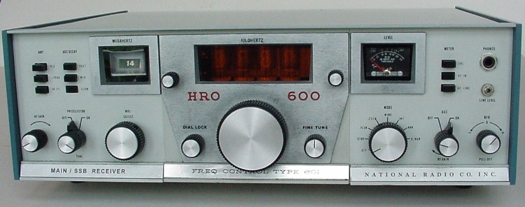 |
| A unique feature of the HRO-600 is its motorized preselector. The 35-position "MHz Select" knob also controls a motorized eleven band preselector. The "Tune" knob (to the left of the "MHz Select" knob) peaks the tuned circuits for optimium response within each range. The preselector is useful when the radio is operated near a strong transmitter (as in shipboard service), but is ordinarily not needed. Note the variable BFO on the right of the radio, which is used for CW reception when one of the four internal CW crystal filters are selected. A fixed BFO is used when the USB and LSB crystal filters are selected. The HRO-600 is filled with crystal filters! |
|
|
The HRO-600 looks positively diminutive, next to the earlier HRO-500 receiver (shown mounted atop an LF-10 low frequency preselector). Performance-wise, however, the HRO-600 runs circles around its older brother. Of course, National afficionados believe there can never be an adequate substitute for the legendary "PW" dial, a fixture of all HRO receivers, until it was at last supplanted by the HRO-600's digital frequency display. |
| SPECIFICATIONS: The HRO-600 spans the frequency range of 16 kHZ to 30MHz (with five bands below 1 MHz) and receives SSB, CW, AM, and A2. Optional accessories are the Model 650 FSK convertor, Model 640 ISB adaptor, Model 610 DC power supply, and rack mounting brackets. The frequency stability is specified (with the 601 plug-in VFO) as less than a 20 Hz drift in 15 minutes. The receiver features three AGC time constants (0.1 Sec, 0.5 Sec, and 2 Sec), greater than 90 dB image rejection, and six selectivity settings provided by 8-pole 5 MHz crystal filters. The HRO-600 can sustain 30V of RF (18 Watts!) applied directly to the 50 ohm antenna input, and IMD is negligible for RF levels below 100 mV. Other features of the receiver include a switchable 20 dB attenuator, a variable line audio output, and a high Z antenna input (as well as the customary 50 ohm input). It may be powered from either 115 or 240 VAC and has a small internal monitoring speaker. Click HERE to view a complete list of specifications in a new window. |
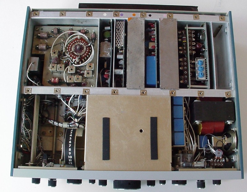 |
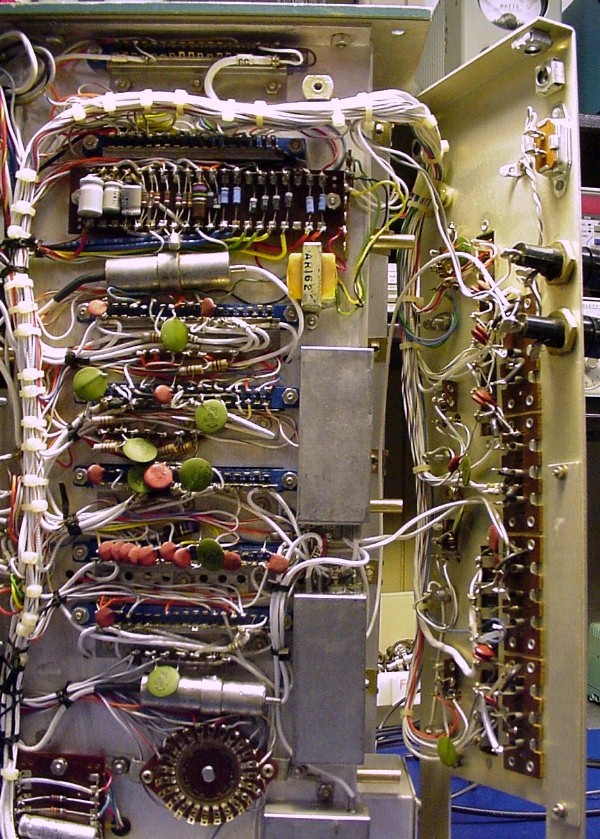
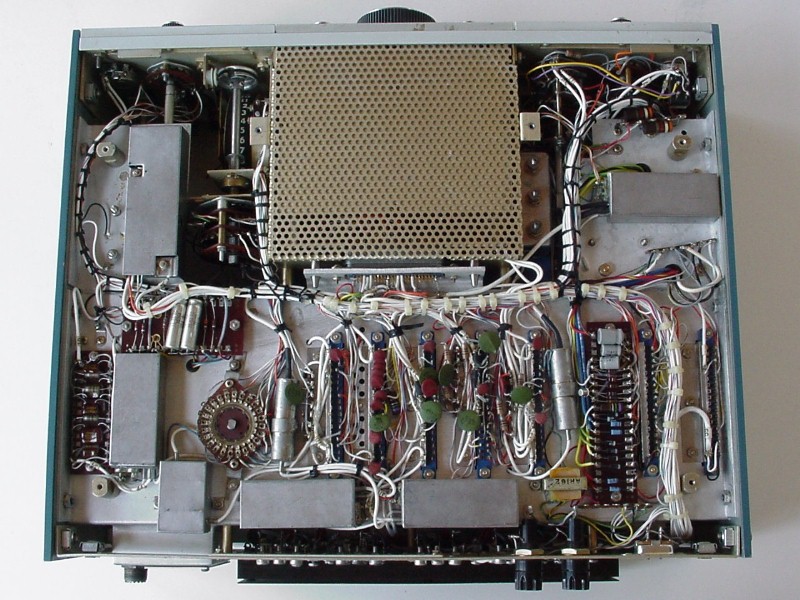
| CONSTRUCTION DETAILS:This under-the-hood view of the HRO-600 shows the preselector at the left rear, with its motorized 11-band selector switch. Most of the radio's circuitry is housed on vertically mounted plug-in printed circuit modules. Moving from left to right at the rear are the "front end module," the "1st injection synthesizer module," the "2nd mixer module," the "2nd injection/AF amplifier module," and the power supply regulator and filter capacitor modules. In the front, the blue IF crystal filters can be seen next to the power transformer and internal speaker. The plug-in VFO is concealed below the aluminum cover in the front center of the radio. The HRO-600 circuitry is all solid-state and uses a combination of Si bipolar transistors, JFETs, and early Motorola MECL integrated circuits. |
|
Most of the HRO-600's "mainframe" wiring consists of interconnects for the 36-pin circuit board edge connectors. Teflon-insulated wire is used for all point-to-point wiring, and all shielded cables are marked with identifying numbers. The rear panel folds out (right photo) to provide access to the rear connector wiring. |
 |
|
|
|
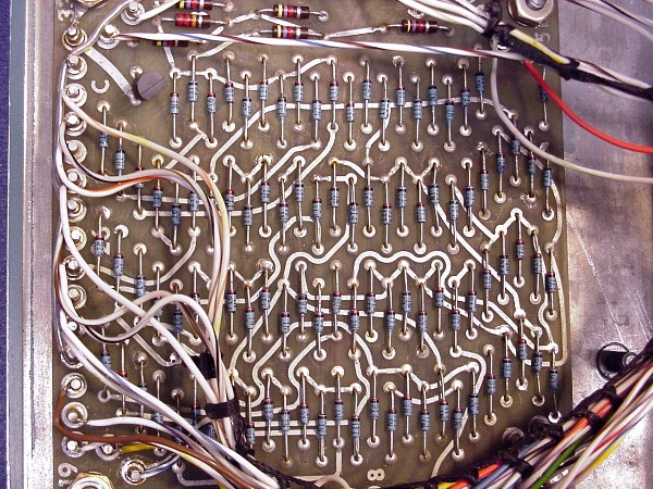
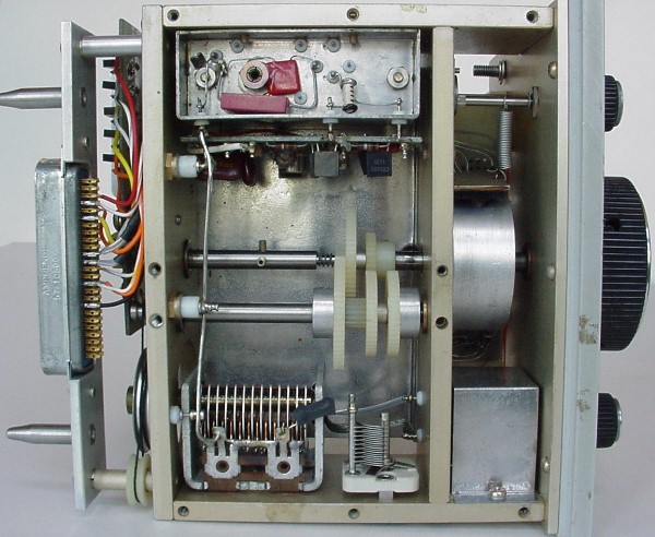
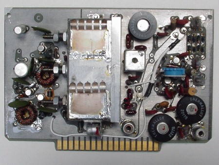 Circuit modules are fabricated on double-sided fiberglass circuit boards. Shown here is the front-end/1st mixer module. Circuit modules are fabricated on double-sided fiberglass circuit boards. Shown here is the front-end/1st mixer module. |
Diodes, diodes, everywhere. This diode matrix is used to decode the MHz band selector. |
 The motor driven 11-band preselector is ganged to the "MHz Select" switch and provides excellent front-end selectivity. The motor driven 11-band preselector is ganged to the "MHz Select" switch and provides excellent front-end selectivity. |
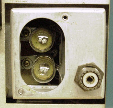 If you accidentally transmit into the receiver, these light bulbs, replaceable from the rear panel, will save your radio. If you accidentally transmit into the receiver, these light bulbs, replaceable from the rear panel, will save your radio. |
|
|
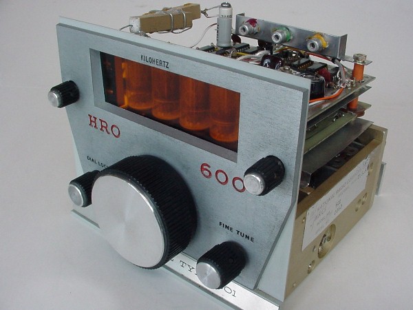
A unique feature of the HRO-600 is its plug-in frequency control options. Shown here is the Model 601 tunable VFO module, which features a four-digit Nixie tube display. The VFO slides into an opening in the radio's front panel and seats into a 50-pin Centronics type connector. The two upper knobs lock the unit into place. Color-coded shielded cables carry the VFO's 4-5 MHz output, a 5 MHz fixed BFO output, and also a 5 MHz negative logic clock used by the synthesizer. The 5 MHz oscillators are oven-stabilized. For specialized uses, a Model 602 thumbwheel-operated frequency synthesizer (with no frequency display) was also available, as was a Model 603 crystal oscillator (users could select 12 crystals in the 4-5 MHz range). Obviously, most users preferred the versatility of the Model 601 VFO. |
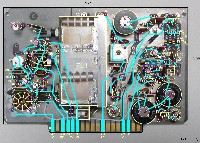
| This side view of the Model 601 VFO reveals a high level of complexity, with two stacked printed circuit boards. The frequency counter/Nixie display driver circuitry is on the upper board, while the lower board houses the fixed 5 MHz reference oscillators and some of the VFO electronics. | 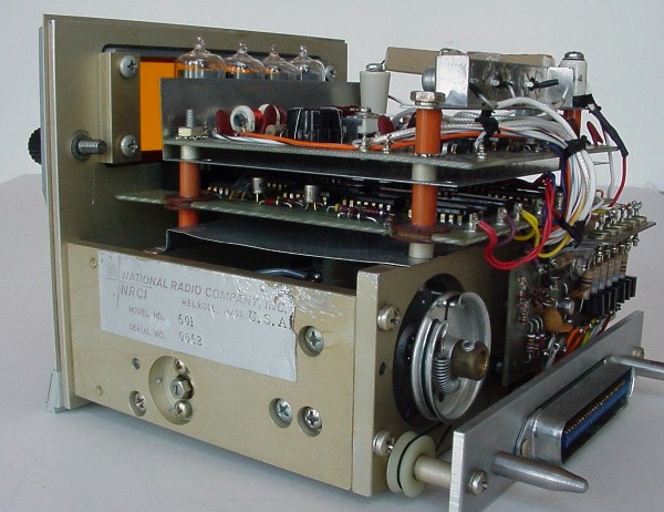 |
 |
The excellent frequency stability of the VFO is a result of its rugged mechanical design. The VFO housing is fabricated from thick machined aluminum plates, and the frequency-controlling elements (such as the fixed capacitors visible at the top of the photo) are carefully shielded. The nylon gear assembly is for the VFO's ingenious two-speed tuning feature. Pulling out the main tuning knob changes the tuning rate from its normal 5 kHz/revolution to 100 kHz/revolution. Oddly, given the care given to the VFO design, the linkage to the main tuning capacior uses a simple pulley & dial cord coupling. Other receivers in this price class would typically use antibacklash gear coupling. |
|
CIRCUIT DESCRIPTION: (Please refer to the simplified block diagram, which you can open in a new window by clicking HERE.) When tuning signals from 16 kHz to 1 MHz, the HRO-600 acts as a single conversion receiver. In this range, the received signal is added to the 4-5 MHz VFO output, resulting in a fixed 5 MHz IF. After amplification, the IF output passes through a wideband 8 kHz crystal filter, and then, if desired, through addtional narrower bandwidth crystal filters. The amplified and filtered 5 MHz signal is then detected by the product detector/BFO, and the detected audio is then amplified by both a line audio amplifier and a speaker amplifier. AGC is IF-derived and is applied to several of the amplifier stages. When tuning signals above 1 MHz, the HRO-600 uses a double conversion scheme. The 1 -30 MHz signal frequency is mixed with the 56-84 MHz output of the first injection synthesizer, with resulting difference signals falling in the range 55 - 54 MHz. This difference signal is then mixed again with a variable 50-49 MHz local oscillator to produce a 5 MHz fixed IF. Subsequent processing is identical to that described in the preceding paragraph. The most complicated part of the HRO-600 is the frequency synthesizer, which produces 56-84 MHz sine waves in 1 MHz steps. This circuit is a phase-locked-loop design and uses a voltage controlled oscillator in combination with a programmable frequency divider. When this circuit was designed in the mid-1960s, integrated circuits had limited functionality, and the designers had to engineer the digital logic from the ground up using flip-flops, and gates. To further complicate matters, the circuit logic used a very early family of now-obsolete Motorala emitter-coupled-logic (ECL) ICs. These ICs use negative voltage logic, requiring the HRO-600's power supply to produce several negative as well as positive voltages. |
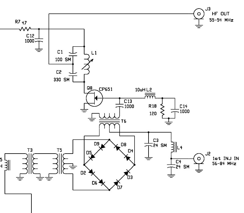 |
In contrast to the synthesizer design, the RF circuits in the HRO-600 are straightforward and surprisingly contemporary. For example, the 1st mixer, shown at left, uses a balanced diode ring for wide dynamic range, and field effect transistors for the output amplifier stage. These circuit concepts were definitely state-of-the-art when the HRO-600 was designed in the 1960s. Click HERE to view the entire front-end schematic diagram in a new window. |
|
RESTORATION AND A TALE OF WOE: I knew when I bought it that the radio was dead on all HF bands, so I expected to face some repair problems. Fortunately, an original manual had come with the radio, so I figured troubleshooting would be straightforward. I figured wrong. There were two big complicating factors. First, the manual only included circuit diagrams of the mainframe interconnections. National had expected users to send defective circuit board modules back to the factory for repair, and try as I might, I couldn't find any board-level schematics. In short, I hadn't a clue what was inside all those circuit board modules! Second, the dead bands turned out to be caused by a defective 1st injection phase-lock-loop synthesizer. Aside from the fact that I knew nothing about synthesizer design, and had no schematic diagram to guide me, the synthesizer module was filled with long-obsolete Motorola integrated circuits. Fortunately, the story does have a happy ending, which you can read about by clicking HERE on the banner at the bottom of the page. |
|
OPERATING IMPRESSIONS: The HRO-600 is a surprisingly good performer. The audio is crisp and clear, and the selectivity is excellent, as one would expect from the 8-pole crystal filters. SSB and CW signals have a very clear tone, quite unlike signals on the HRO-500, which made CW notes sound like they were being played on a harmonica. The stability is excellent, with no discernable drift. The sensitivity is also excellent, even on the higher bands. The receiver really shines on the VLF bands, thanks to the built-in preselector. The bandswitch has six bands below 1 MHz, each tuning an octave (16-32 kHz, 32-64 kHz, etc.), and the preselector peaks up sharply on signals within each band. Changing the bandswitch engages the motor, and there is some whirring for a second or so, until the preselector settles into its designated range. Quite a unique feature. The AGC time constants seem well-chosen, and the attack time is sufficiently short that I couldn't hear thumping on CW signals. The gain distribution among the receiver stages seems well thought out, because the receiver seems lively but not noisy. My only quibbles with the HRO-600 are that the 0.1 kHz Nixie tube flickers between digits, which I find distracting, and secondly, that the feel of the main tuning knob has just a tinge of sponginess, a result no doubt of the simple dial cord linkage to the VFO capacitor. Maybe I'm just spoiled from the solid heft of the PW dial. All-in-all, the HRO-600 was a pleasant surprise, performance-wise. I'd rate it roughly on a par with the Drake DSR-1 or DSR-2, which were a later design. The tuning is superior to that of the Drake receivers, which had a clunky way of changing bands, but then the Drake radios had an effective noise blanker, which the HRO-600 lacks. The radio's performance is definitely better than that of the analog Collins 51S1, which was a contemporary of the HRO-600 but was based on an older technology. |
|
CLICK HERE or on the photo to go to the HRO-600 Restoration Page
|
 |
![]()
![]()
![]()
![]()

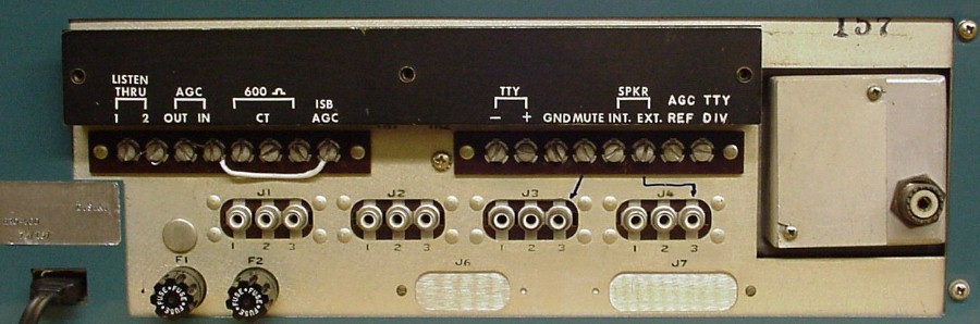 Typical of commercial grade receivers, a full array of audio and IF outputs is available on the HRO-600's rear panel.