|
|
Collins KWS-1 Blower Bearing Replacement |
|
|
|
Collins KWS-1 Blower Bearing Replacement |
|
|
A KWS-1 blower that "rattles" is a common problem and a symptom of worn-out motor bearings. The bearings can be easily replaced, although you'd better plan on committing several hours to the project. Here's all the information you need to replace the bearings in your KWS-1 blower motor. The basic procedure is first to remove the blower from the KWS-1, which requires removal of the plate transformer (not a big job). The motor is then removed from the blower and disassembled. After the old bearings are removed and replaced, the blower is reassembled and placed back in the KWS-1. This procedure is straightforward, even for someone (like myself) who has never replaced motor bearings before. Now for the details . . . |
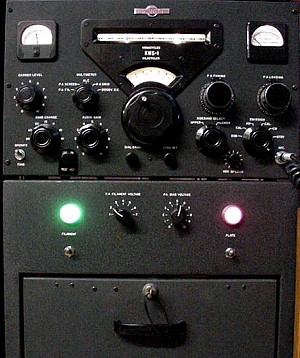
The Collins KWS-1 is a deluxe high power amateur band transmitter. Paired with its matching 75A-4 receiver, these "gold dust twins" represented the "creme de la creme" ham station for well-heeled amateurs in the mid-1950s. |
|
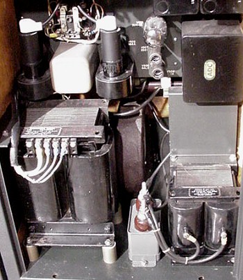
The squirrel cage blower housing is visible behind the oil-filled capacitor in the center of this power supply photo. It's easily removed, once you remove the plate transformer. |
The bearing part number is WC87038 (8x22x.406) felt seal ball bearings. Price is $5.50 each. You'll need two bearings.
|
|
Before you get started, you'll need the following items: * flat-end and phillips screwdrivers (short and long shaft) Now . . . . here are the step-by-step instructions: (1) Unplug the transmitter and clear a space around it. Remove the power supply door and the back panel (secured with 16 phillips head black screws). (2) Reaching in through the rear opening, unscrew the two motor wires from the terminal block, and the clamp securing the fabric to the blower outlet. Then, using a large phillips screwdriver, remove the four mounting screws and the large washers on the blower shock mounts. Remove the four screws securing the blower to its shock mounting plate and take the mounting plate from the compartment. Don't bother trying to remove the blower: it won't fit through the rear opening. Hint: take care not to bump the fragile power resistors above the blower. |
|
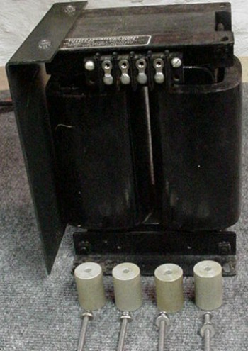
The KWS-1 power transformer sits on four aluminum blocks. Connections are made to top-mounted terminal blocks on the front and rear of the transformer. Note the side metal plate, which is not removed. |
(3) Slide the KWS-1 plate transformer out the front after first disconnecting the wires from the front and rear terminal blocks, and then removing the four long screws holding the transformer to its aluminum mounting blocks. Move the blower out of the way to gain access to the rear screws. Once the transformer is out of the way, you can then remove the blower from the compartment. Hint: a long-bladed screwdriver and flashlight will aid in reaching the screws on the rear terminal block. Hint: No need to remove the two screws securing the side metal plate to the transformer. Hint: Write down the colors of the wires going to the terminals. |
|
|
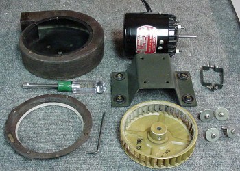
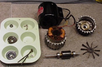
The major components of the blower assembly are the impeller housing, the impeller cover, the impeller, the shock mounting bracket, and the motor. Disassembly requires a nut driver and allen key. |
(4) Separate the motor from the blower assembly by removing the impeller cover plate, impeller, and mounting screws (behind the impeller). (5) Once the motor is free, slide it out of its metal housing, which is secured with four screws. Be careful not to pinch the wires. Hint: If the housing doesn't slide off, it's probably catching on the pins securing the motor ID plate. If so, pop off the ID plate. |
|
|
The disassembled motor consists of the the black metal housing, the front and rear castings, the windings (shown mounted in the rear casting, the armature and bearings, and the rear cooling fan. |
(6) Pop the small 10-bladed fan off the rear motor shaft with a screwdriver. Hint: Make a note of the orientation of the fan on the shaft. (7) Remove the two aluminum spacer-nuts attached to the long screws that hold the motor casing together. Hint: Don't remove the other two spacer-nuts, or the bearing covers. |
|
|
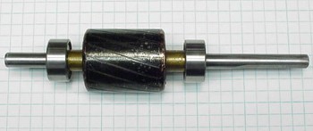
(8) Slide the front of the motor casing off and remove the armature and bearing assembly. Hint: Note the position of the washers on the armature shaft. (9) Remove the old bearings from the shaft. You can try prying them off with a screwdriver, but if they won't budge (mine didn't) you'll need to use a bearing puller. Once they've slid about a 1/4 inch, they'll move easily. Don't hammer on the shaft for any reason! (10) Using fine steel wool or emory paper, polish the shaft and remove any congealed gunk. While you're at it, clean the surfaces on the motor housing that the bearings slide into.
(11) Slide the replacement bearings onto the shaft, tapping them into final position with a wood block and small hammer. Note that the bearings slide all the way down the shaft until they touch the brass spacers, as shown above. |
||
|
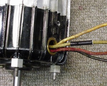
(12) Reassemble the motor, securing it with the two long screws and spacer-nuts. Hint: Make sure the casings are carefully lined up with the screw holes on the windings BEFORE you slide everything together. (13) Check the insulation on the motor wires and repair any frayed spots (below). Hint: Note the paired wire colors if you need to clip off the terminals.
|
||
|
(14) Reattach the 10-bladed fan to the rear shaft of the motor. If it wobbles on the shaft, tap its bushing firmly with a sharp center punch to fix it in place. Bend the fan blades as needed, to make sure they rotate uniformly. (15) Slide the motor into its metal housing and reassemble the blower. Test the blower out on your bench (apply 120VAC) to make sure it rotates smoothly and quietly. Don't reattach the blower to the shock mounting plate, yet. (16) Set the blower loosely into the rear of the power supply compartment, and reattach the plate transformer. Expect to spend a few minutes lining up the aluminum spacers with their mounting holes, but have patience -- it can be done! Reattach the wires to the transformer terminal blocks. Hint: A long-bladed screw starter and flashlight will facilitate attaching wires to the rear terminal block. (17) Once the plate transformer is installed, slide the shock mounting plate through the rear of the enclosure and attach it to the blower. Then secure the blower assembly to the rubber shock mounts, reattach the wires to the terminal strip, and clamp the fabric to the blower outlet. One of the mounting screws is most easily reached from the front of the power supply enclosure. (18) Check to make sure no hardware is left behind, that all wires are dressed neatly and that everything inside the power supply looks in order. Then reattach the back panel, install the front cover, and go celebrate. You're done and will be rewarded for many years with a quiet, smooth-sounding transmitter. Congratulations! |
||
|
|
|
|