|
160m/80m |
|
|||||||||
|
160m/80m |
|
|||||||||
Overview
| These pages describe a homebrew 160m/80m duo-band linear amplifier designed and built over a three year period, and placed in service (finally!) in 2017. This amplifier is intended for CW, SSB, and RTTY and is designed conservatively for continuous duty (key down) operation in any mode at 1500W RF output, with an additional 3 db of headroom to minimize IMD products or damage caused by accidental mistuning, wrong antennas, etc., all of which the builder is prone to. As described below, the amplifier has a number of unusual circuit features. The parts cost for the RF deck and power supply was approximately $4000. |
|
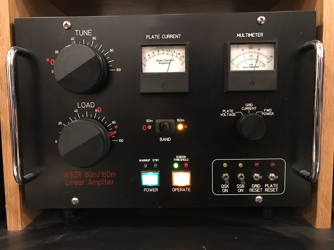
Description: The duo-band amplifier uses three Russian GU74B grid-driven tetrodes, with a total plate dissipation of about 2400W. The drive power is either 5W or 50W for full output, depending on an internal jumper setting. The amplifier uses a pi-L output tank and selects bands with a front panel toggle switch. It is manually tuned, but designed so that typically no adjustment of the tune and load controls is required when changing bands. The amplifier is protected with control grid, screen grid, and plate current overload circuits (resettable by front panel switches). In addition, a protection circuit instantly disconnects the screen voltage should the plate voltage fail for any reason. Additional circuitry protects amplfier components from flashovers or internal tube arcs. The amplifier has QSK keying capability (electronic bias and vacuum relays for T/R switching), and uses a three-tiered control grid bias circuit that reduces heat dissipation in both CW/RTTY and SSB. A digital timer sets the warmup delay to 180 seconds. The adjustable screen voltage (325 VDC nominal) is tightly regulated, as is the control grid bias (-120V, -62V, -50V). A Bird wattmeter line section monitors the forward RF power. The QSK circuit is described in June 2015 QST. The separate HV power supply uses a CMOS logic circuit to arbitrate among three connected RF decks and supplies 2500V at up to 1.8A. The custom Peter Dahl plate transformer weighs 67 lbs. The HV power supply is described in May/June 2013 QEX. The enclosures for both the RF deck and power supply are homemade, with front and rear panels made of 1/8 inch aluminum plate. A frame for the enclosures is fabricated from 1/2 inch square aluminum stock. All external surfaces are powdercoated, and front and rear panels use engraved lettering. |
 |
 |
|
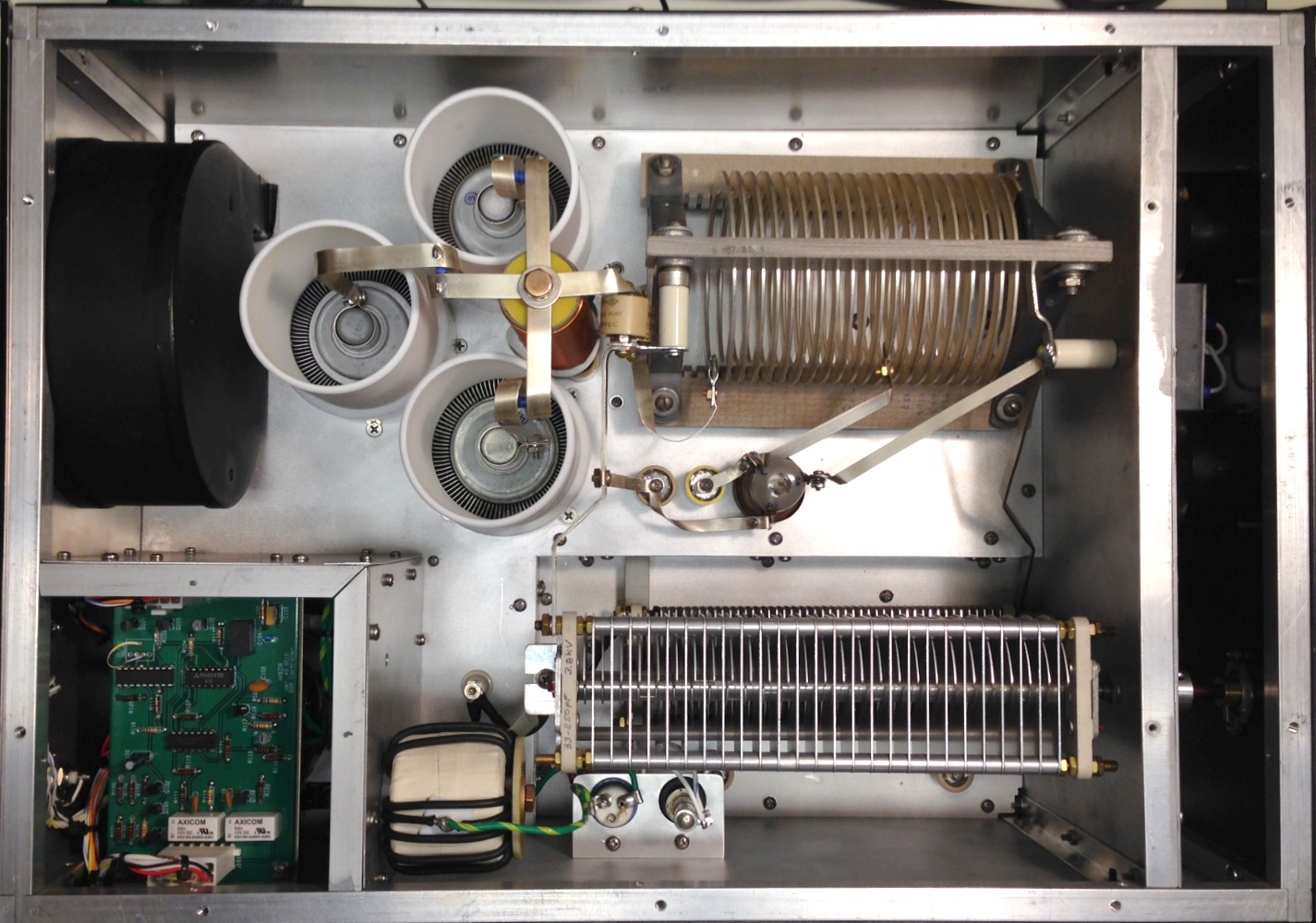
This interior top view shows the three GU74B tetrodes, with their teflon air venting sleeves. The tank inductor of 16.5 uH was fabricated from an AM broadcast band transmitter. The plate and load tuning capacitors are at the bottom right of the photo, and the vacuum relay used as the "bandswitch" is at the center, to the right of the bottom tube. The QSK printed circuit board is in a shielded enclosure at the bottom left and below it (not visible) is a custom screen voltage and filament transformer. The large toroidal inductor is the L2 inductor for the tank circuit. Not visible is a large printed circuit board that the front panel components attach to, minimizing point-to-point wiring. |
|
|
|
|
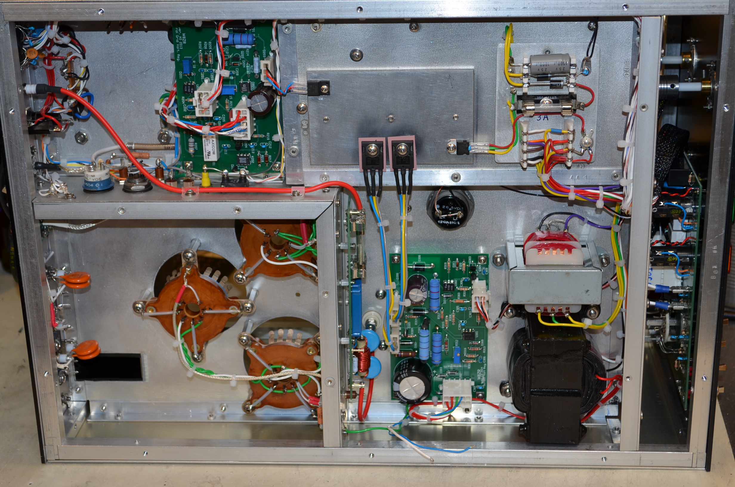
This underchassis view shows the sealed tube socket subchassis on the bottom left of the photo, and to its right the screen voltage regulator PCB, and bias and 12V transformers. The vertical PCB mounted on the right side of the tube subchassis is a fused HV monitoring circuit. The 1/4 inch aluminum plate in the upper middle is a heatsink for the four regulator transistors. The PCB in the upper left regulates the control grid bias voltage, and to its left, on the outside of the tube subchassis are two Jennings RJ1A vacuum relays for T/R switching. Note the relays, which are mounted in large rubber grommets, face in opposite directions to facilitate wiring. The four orange disc capacitors on the left side of the tube subchassis are part of the 50 ohm input attenuator that provides a passive load for the amplifier exciter and, depending on a jumper, a 1:10 attenuator. Just visible behind the front panel is a large PCB for most of the front panel components. There are a total of six printed circuit boards in the RF deck, including the QSK PCB visible only from the top. |
|
|
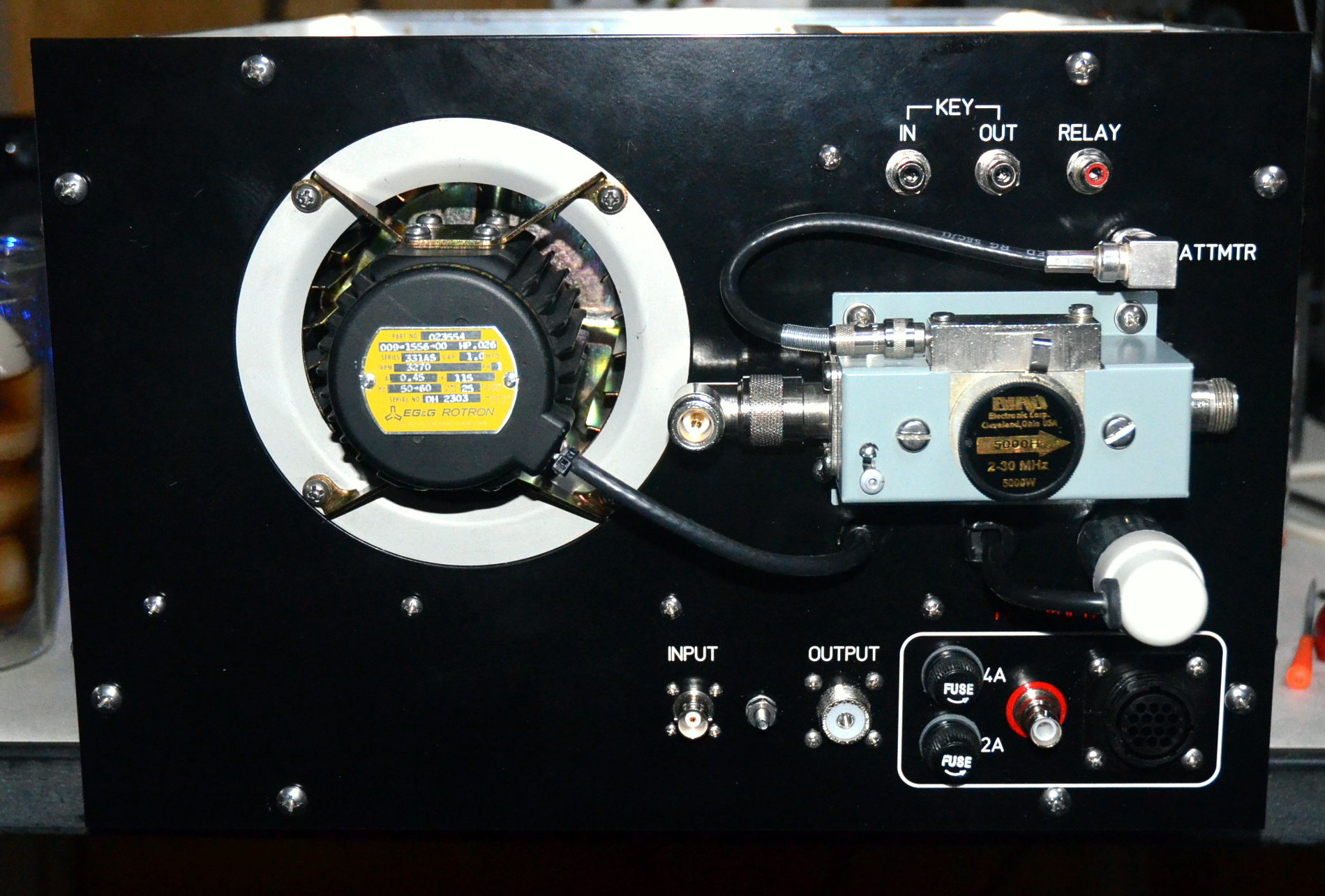
As shown on the right, the blower motor mounts on the outside of the rear panel. Air is drawn in around the motor and pressurizes the tube subchassis. If blower noise is objectionable, the motor and impeller can be removed as a solid assembly (by unfastening the four mounting screws) and replaced with a flange and flexible hose to a remote external blower. A Bird RF line section monitors the RF forward output power. A standard Bird 1000H slug was recalibrated to provide 3000W full scale with a 50uA panel meter. (Bird wattmeters normally require a 30uA movement.) A short coax jumper (not shown) normally runs from the amplifier output SO239 connector to the input of the Bird line section. The three RCA phono jacks at the top right of the panel are for keying the amplifier. The "RELAY" jack is for conventional (non-QSK) keying, while the KEY IN/OUT jacks are for full QSK. In either case, the T/R relays are properly sequenced to prevent hot-switching. The BNC connector with the red ring is for the HV cable from the power supply. It is a special "reverse polarity" SHV connector designed specifically for high voltages and cannot mate with an ordinary BNC connector. |
 |
|
|
|
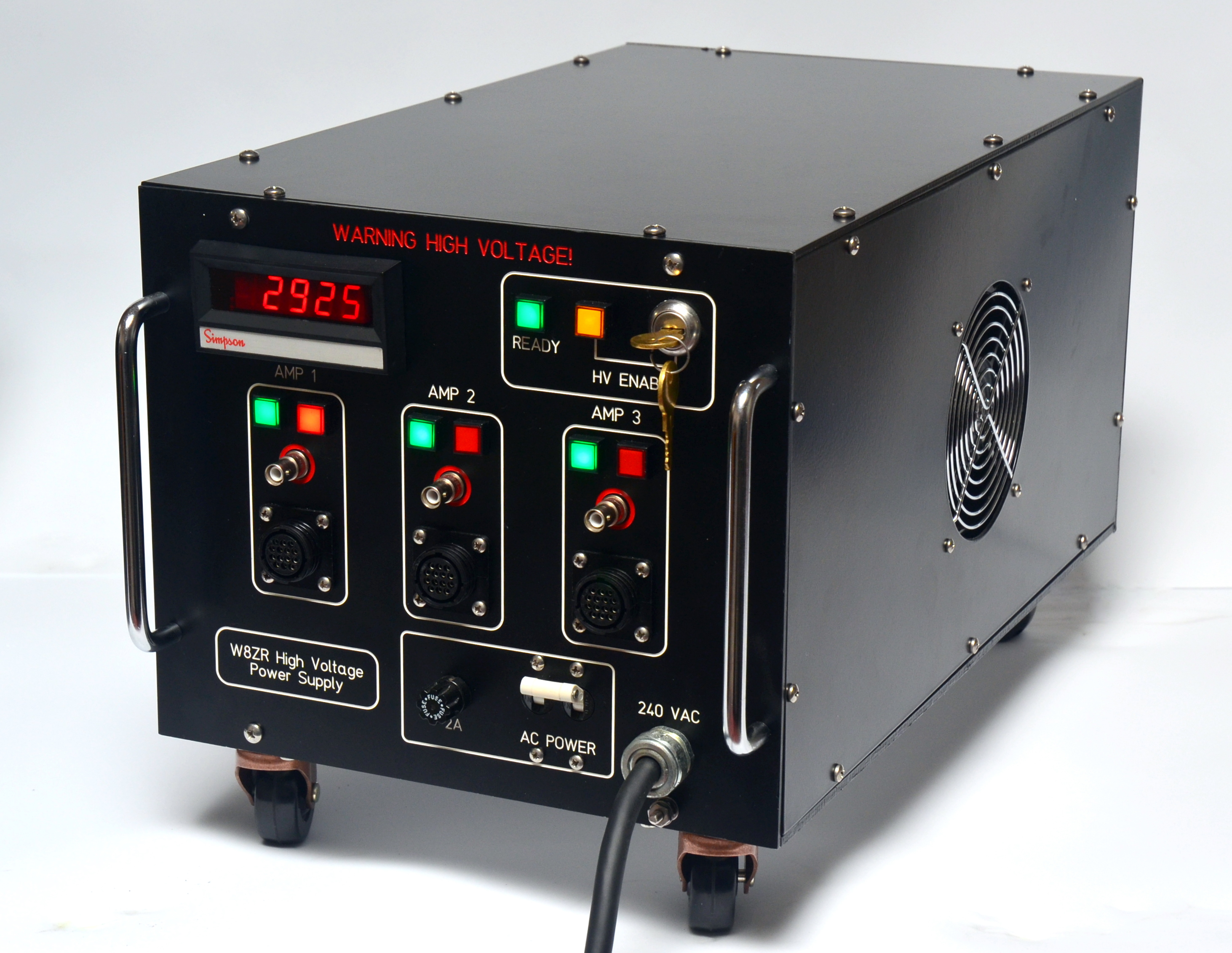
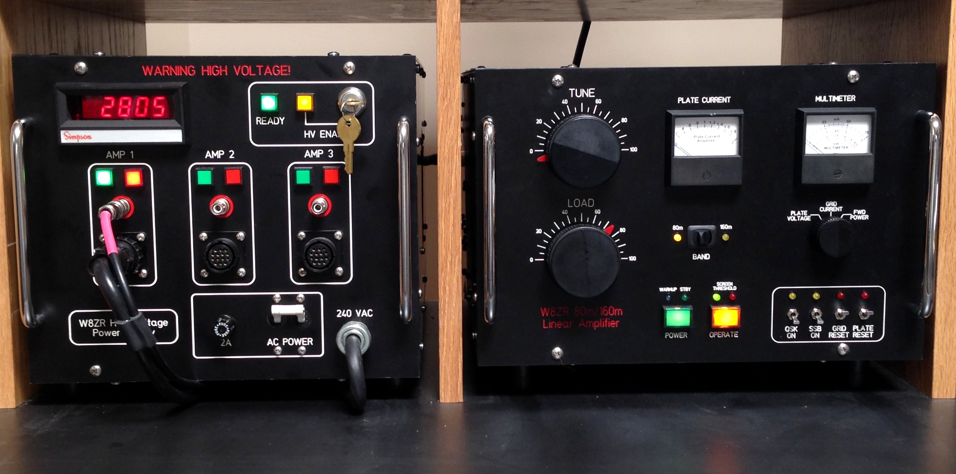
The high voltage power supply has three internal transformer taps that provide a nominal DC output of 2500V, 2700V, or 2900V. The HV supply can power up to three RF decks simultaneously, each with its own control cable and HV cable.The CMOS logic circuitry allows the filament, bias, LV and blower circuits of the RF decks to be on concurrently, but allows only one RF deck to come on-line at a time. (The most recently enabled RF deck steals control and disables any other on-line RF decks.) The output HV is available only to the selected RF deck and is routed to its HV connector by vacuum relays specifically designed for DC high voltage switching. A key-operated safety switch disables the HV circuitry but allows the control circuits to remain active, and an integral magnetic circuit breaker is in series with the 240VAC primary line. A quiet muffin fan circulates air over the internal components. |
|
|
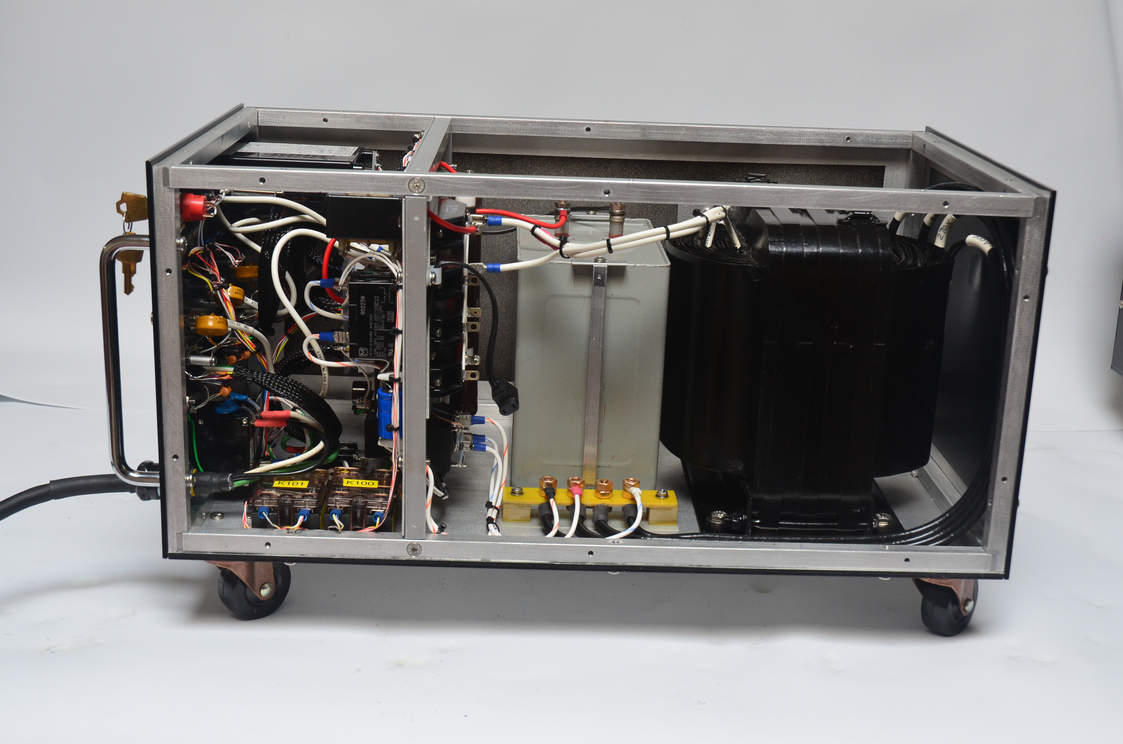
The HV power supply weighs about 120 lbs (half of which is the plate transformer) and rests on a bottom plate of 3/16 inch thick aluminum. The metal frame is fabricated from 1/2 inch aluminum stock. The CMOS logic circuits are mounted on the front side of the sub-panel, and the rectifier diode blocks and bleeder resistors on the back side. The high voltage circuitry is a straightforward bridge rectifier, with a 50uF capacitor input filter.The front panel tilts down for servicing. Two nearly identical power supplies were constructed, one for amplifiers using the GU74B or 3CX800A7, and the other for amplifiers with tubes requiring higher voltages, such as the 8877. |
|
|
Click on the "RF Deck Construction" and "Power Supply Construction" links at the top of the page for many additional photos, details, and homebrew tips.
Please let me know if you have any comments or suggestions about this website. I welcome email. Thanks for looking!