|
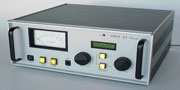
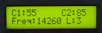
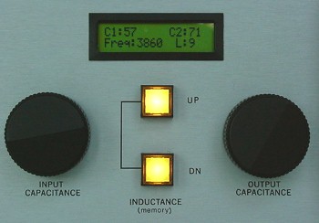
In the manual mode, the EZ-Tuner has the "feel" of an ordinary antenna tuner, with knob-controlled variable capacitors and pushbutton-operated inductor switch. An LCD display (right) shows current settings and operating frequency, and a large meter shows reflected or forward RF power.
|
|
|
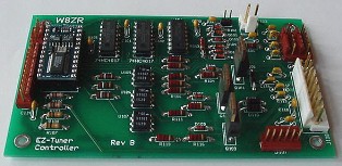
There's a lot of computing muscle in the EZ-Tuner's BASIC Stamp BS2sx microcontroller, shown at the upper left of the 3x5 inch controller circuit board. Other components on the board monitor the transmit frequency, power the inductor solenoid, provide logic signals for the stepper motor drivers, and control two relays. All driver circuits are optically isolated. Note this is a later revision of the circuit board shown in May 2002 QST.
|
In the automatic mode, the EZ-Tuner's built-in frequency counter tracks the transmitter frequency and updates the capacitors and inductor as necessary. Band-switching is automatic and takes only a few seconds.
Technically, the EZ-Tuner is a "memory tuner," since it relies on stored settings rather than a search algorithm to find a match. Although it's an effort to store the initial settings, one then doesn't have to worry about arcing and amplifier damage while the tuner searches for a match. Fully-automatic tuners work best for 100 W class transceivers, whose shut-down circuits protect against a mismatched load. If there are no customized settings at the frequency in use, the tuner defaults to the settings for a 50 ohm (1:1) match.
|
|
The EZ-Tuner powers up in the automatic mode. After displaying a startup message and initializing the circuitry, the controller then moves the capacitors and inductor to their last-used settings. This auto-recovery feature means that the tuner can be operated remotely, without concern about power failures.
Once powered up, the tuner looks continuously for the presence of an RF signal. Whenever it detects a signal, it verifies that the frequency is in a valid amateur band and then moves the capacitors and inductors to the appropriate memorized settings. The 134 memories subdivide each amateur band into segments, which range in width from 10 kHz for 160 meters, to 50kHz for 10 meters. In addition to tracking frequencies automatically, the tuner can be stepped through its memories using the front-panel up/down buttons.
|
|
|
Turning either of the front panel knobs (left) switches the tuner into manual mode. In this mode, optical encoder-controlled stepper motors tune the variable capacitors with a 5:1 electronic "vernier" and the up/down buttons step the inductor through 11 possible settings. Briefly pressing the "mode/store" button toggles the tuner back to the automatic mode, and holding the button in for 0.5 second stores the settings in memory. Another pushbutton toggles the tuner on-line or off-line.
|
|
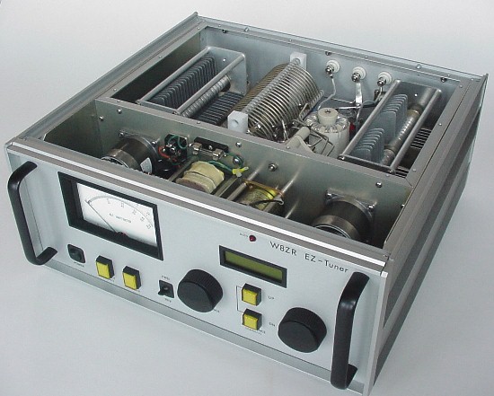
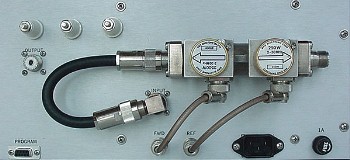
Under the hood of the EZ-Tuner (below) is a shielded RF compartment which contains two Cardwell-Johnson 3500V variable capacitors, two 50pF/5kV fixed capacitors, a 20.5 uH tapped inductor (made of 3/16 inch silver-plated copper tubing and 3 in B&W coil stock), a dual-section 11-position ceramic bandswitch, a 4:1 output toroidal transformer, and two vacuum relays. As shown in the right photo, a Bird dual-linesection RF wattmeter is attached to the rear panel. Also shown in the rear panel photo is the DB-9 programming port and the high-voltage feedthrough insulators for open wire feeders.
|
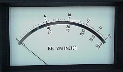
The Bird dual linesection mounted on the rear panel displays full-scale readings of 2500W forward and 100W reflected power on a Coaxial Dynamics 30 uA meter.
|